(1*/,6+,QVWUXFWLRQVPDQXDO
51
7&;
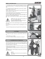
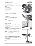
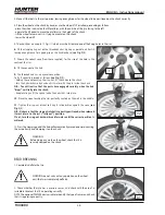
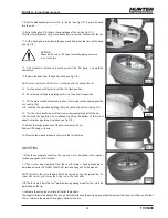
9- Place the mobile bead presser at 180° to the tool (see Fig. O/3) to insert the bead
into the well.
10- Raise the hook until it is above the upper edge of the rim (see Fig. O/3).
To further simplify demounting, move back a few mm towards the centre of the rim.
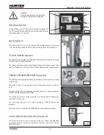
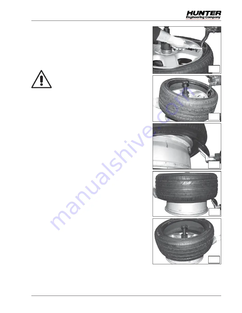
11- Fit the “bead guard” provided in the gap created between the rim and the bead
(see Fig. O/4).
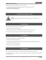
WARNING!
Proceed with care in this stage to avoid applying excessive
stress to the tyre.
12- Start clockwise rotation and continue until the first bead is completely
demounted.
13- Release the bead from the hook by hand (see Fig. O/5).
14
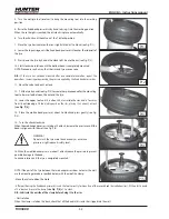
- Move the tool back until the laser is realigned with the edge of the rim.
15- Turn the chuck until the valve is at the 12 o’clock position.
16- Raise the top carriage completely until it is in the out-of-use position.
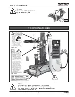
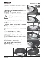
17- Lift the bottom bead breaker disc to about 10 mm above the upper edge of the
rim (see Fig. O/6).
N.B. : Facilitate this operation by lifting the tyre by hand at 6 o’clock (see Fig. O/7).
18- Turn the chuck clockwise until the tyre has come completely out of the rim.
N.B.: Facilitate this operation by simultaneously lifting the bottom of the tyre at
about 2 o’clock and guiding its rotation (see Fig. O/8).
19- Make a thorough inspection of the pressure sensor (if any).
Replace it if damage is found.
20- Move the lower bead breaker disc away to the rest position.
MOUNTING
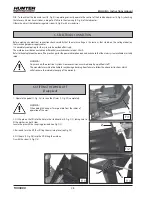
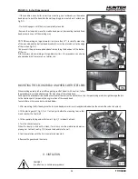
1- Make the appropriate checks on the tyre and rim as described in the relevant
section on page 44 of this manual.
2- If the rim has been removed from the chuck, clamp it again proceeding as
described earlier in the “WHEEL CLAMPING” section on page 45 of this manual.
NOTE: For safety, the valve should ALWAYS be replaced using the special tool.
On
valves with sensor, only change the O-ring seal or the valve body.
N.B.: The tools must be in the “rest” position, leaving enough room for the tyre to be
positioned on the rim.
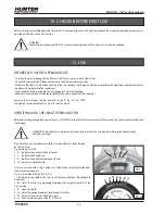
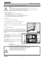
3- Lubricate the entire inner surface of the rim thoroughly.
Thoroughly lubricate the beads of the tyre, on both the inside and the outside, around the whole circumference, over a thickness of at least
30 mm. Lubricate the whole of the upper sidewall of the tyre.
O/6
O/7
O/8
O/4
O/5
Summary of Contents for TCX3000
Page 32: ...32 7 12 0DQXDOH G XVR 7 ...
Page 62: ...62 1 6 QVWUXFWLRQV PDQXDO 7 ...
Page 92: ...92 5 1d 6 0DQXHO G LQVWUXFWLRQV 7 ...
Page 122: ...122 876 HWULHEVDQOHLWXQJ 7 ...

