10
1
3)
Collegare
il
perno
(18,
Fig.
B)
del
cilindro
di
ribaltamento
al
palo
(1,
Fig.
B)
utilizzando
la
vite
TE
(17
Fig.
B)
e
serrando
con
il
dado autobloccante (16, Fig. B).
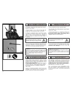
3) Using the screw (17, Fig. B) tighten with the self-locking nut
(16,
Fig.
B)
to
connect
the
pin
(18,
Fig.
B)
of
the
vertical
post
tilting cylinder (1, Fig. B).
12
11
9
17
4)
Togliere
la
fiancata
sinistra
(6,
Fig.
B)
svitando
le
2
viti
(4,
Fig.
B)
e
collegare
il
tubo
pneumatico
(3,
Fig.
B),
proveniente
dal
palo, al raccordo a T (5, Fig. B).
5)
Rimontare
la
fiancata
sinistra
(6,
Fig.
B)
e
serrare
le
2
viti
di
fissaggio (4, Fig. B).
6) Rimuovere il lubrificatore (7, Fig. B) svitando le 2
viti
(8,
Fig.
4)
Remove
the
two
screws
(4,
Fig.
B)
from
the
left
side
panel
(6,
Fig.
B)
and
remove
it.
Connect
the
air
hose
(3,
Fig.
B)
from
the
tower to the “T” connector (5, Fig. B).
5)
Replace
the
side
panel
(6,
Fig.
B)
and
fasten
with
its
screws
(4, Fig. B).
6) Remove the lubricator (7, Fig. B) by removing its two screws
8
14
4
7
15
3
16
5
13
18
14
15
2
B).
7)
Montare
la
protezione
in
plastica
(9,
fig.
B)
e
fissarla
mediante
le 4 viti autofilettanti (10, Fig. B).
8)
Rimontare
il
lubrificatore
(7,
Fig.
B)
riutilizzando
le
2
viti
(8,
Fig. B).
9)
Fissare,
sul
retro
del
palo
(1,
Fig.
B),
la
protezione
in
lamiera
(11, Fig. B) utilizzando le 2 viti autofilettanti (12, Fig. B).
10)
Rimuovere
dalla
paletta
stallonatrice
la
vite
TCEI
(1,
Fig.
B/2),
la
rondella
(2,
Fig.
B/2)
e
il
dado
autobloccante
(3,
Fig.
B/2)
facendo
attenzione
a
mantenere
nella
loro
posizione
le
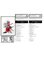
due rondelle di rasamento (4, Fig. B/2).
(8, Fig. B).
7)
Install
the
plastic
guard
and
fix
it
with
the
four
self-tapping
screws (10, Fig. B).
8)
Replace
the
lubricator
(7,
Fig.
B)
using
its
two
screws
(8,
Fig.
B).
9)
Fix
the
metal
sheeting
guard
(11,
Fig.
B)
to
the
back
of
the
tower (1, Fig. B) using the two self-tapping screws (12, Fig. B).
10)
Remove
the
countersunk
cap
screw
(1,
Fig.
B/2),
the
washer
(2,
Fig.
B/2)
and
the
self
-locking
nut
(3,
Fig.
B/2)
from
the
bead
loosener
shoe,
taking
care
to
keep
the
two
shimming
washers
(4, Fig. B/2) in place.
6
2
4
3
B
11)
Posizionare
la
paletta
sul
braccio
stallonatore
(vedi
Fig.
B/2)
prestando
la
massima
attenzione
al
corretto
posizionamento
delle due rondelle di rasamento.
12)
Fissare
la
paletta
al
braccio
utilizzando
la
vite
TCEI
pre-
cedentemente
rimossa
e
i
relativi
dado
e
rondella
(vedi
Fig.
B/2).
FISSAGGIO DEL SERBATOIO
11)
Position
the
shoe
on
the
bead
loosener
arm
(see
Fig.
B/2),
taking
the
utmost
care
to
keep
the
two
shimming
washers
in
their correct positions.
12)
Fix
the
shoe
to
the
arm
with
the
previously
removed
coun-
tersunk
cap
screw
and
the
relative
nut
and
washer
(see
Fig.
B/2).
6.4
6.4
AIR TANK FIXING
(solo TCX525 GP)
(TCX525 GP only)
1
1)
Rimuovere
le
4
viti
TE
M
8x16
già
posizionate
sulla
carcassa
nei fori di fissaggio del serbatoio.
1)
Remove
the
four
M
8x16
hex
screws
from
the
tank
fixing
holes
on the casing.
12
4
B/2
2)
Inserire
il
tubo
in
gomma
(1,
Fig.
B/3)
che
fuoriesce
dalla
carcassa
(2,
Fig.
B/3)
nell'attacco
a
resca
(3,
Fig.
B/3)
del
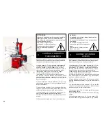
serbatoio (4, Fig. B/3).
2) Fit the rubber tube (1, Fig. B/3) that projects from the casing
(2, Fig. B/3) into the tank (4, Fig. B/3) connection (3, Fig. B/3).
3) Position the tank on the casing and fix it in place with the


