

10
42216-01 • 05/02/12 • Hunter Fan Company
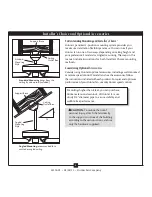
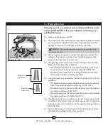
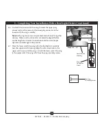
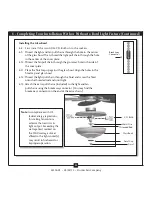
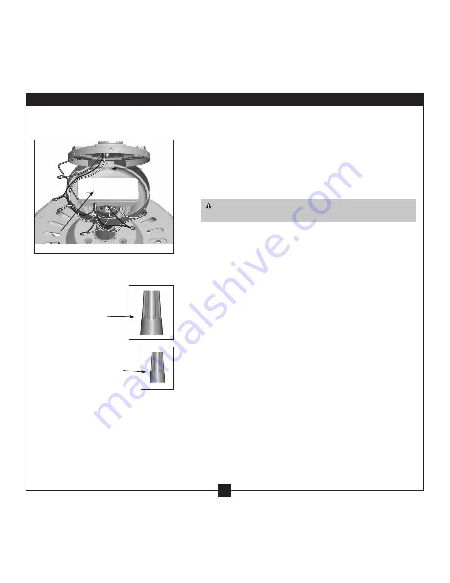
Large Wire
Connector
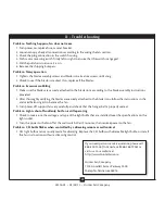
Steps 5-3 – 5-7
Antenna
Receiver
Small Wire
Connector
All wiring must be in accordance with national and local electrical
codes and ANSI/NFPA 70. If you are unfamiliar with wiring, use a
qualified electrician.
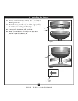
5-1. Make sure the power is still off.
5-2. To connect the wires, hold the bare metal leads together and place
a wire connector over them, then twist clockwise until tight. For
all these connections use the wire connectors provided.
CAUTION:
Be sure no bare wire or wire strands are visible after
making connections.
5-3. Using a large wire connector, connect the ground wire from the
ceiling to the green ground wire from the ceiling plate and the
green ground wire from the downrod.
5-4. Using the large wire connectors, connect the white wire and the
black wire from the ceiling as follows:
• The white (common) power wire from the ceiling to the white
wire from the receiver (marked on red tag “NEUTRAL IN”)
• The black power wire from the ceiling to the black wire from
the receiver (marked on red tag “LIVE IN”)
5-5. Using the small wire connectors, connect the wires from the fan
as follows:
• The black wire with a white stripe from the fan to the red wire
from the receiver (marked on white tag “LIGHT OUT”)
• The black wire from the fan to the black wire from the receiver
(marked on white tag “FAN OUT”)
• The white wire from the fan to the white wire from the receiver
(marked on white tag “COMMON OUT”)
5-6. Check each connection to make sure no bare wire or wire strands
are visible. Push all wires and wire connectors, except for the white
antenna wire from the receiver, back through the ceiling plate into
the outlet box.
5-7. Position the receiver in the canopy so that the antenna is close to
the edge of the ceiling plate for clear reception.
5 • Wiring the Fan


