background image

DECLARATIONS

27

U.S. Radio Frequency FCC Compliance

FCC ID information is located behind the motor-side end cap. The end cap may be removed to view this 

information.
This device complies with Part 15 of the FCC Rules. Operation is subject to the following two conditions:  

(1) This device may not cause harmful interference, and  

(2) This device must accept any interference received, including interference that may cause undesired 

operation.
This equipment has been tested and found to comply with the limits for a Class B digital device, pursuant 

to Part 15 of the FCC Rules. These limits are designed to provide reasonable protection against harmful 

interference in a residential installation. This equipment generates, uses and can radiate radio frequency 

energy and, if not installed and used in accordance with the instructions, may cause harmful interference 

to radio communications. However, there is no guarantee that interference will not occur in a particular 

installation. If this equipment does cause harmful interference to radio or television reception, which 

can be determined by turning the equipment off and on, the user is encouraged to try to correct the 

interference by one or more of the following measures:

• Reorient or relocate the receiving antenna.

• Increase the separation between the equipment and receiver.

• Connect the equipment into an outlet on a circuit different from that to which the receiver is 

connected.

• Consult the dealer or an experienced radio/TV technician for help.
Any changes or modifications not expressly approved by the party responsible for compliance could void 

the user’s authority to operate the equipment.
This equipment complies with FCC radiation exposure limits set forth for an uncontrolled environment 

and meets the FCC radio frequency (RF) Exposure Guidelines. This equipment should be installed and 

operated keeping the radiator at least 20 cm or more away from person’s body. RF Exposure requirements 

are met when installed in mobile equipment. This module cannot be installed in portable equipment 

without further testing and a change to FCC’s grant of authorization.

Innovation, Science and Economic Development Canada

Innovation, Science and Economic Development Canada Under Innovation, Science and Economic 

Development Canada’s regulations, this radio transmitter may only operate using an antenna of a 

type and maximum (or lesser) gain approved for the transmitter by Innovation, Science and Economic 

Development Canada. To reduce potential radio interference to other users, the antenna type and its 

gain should be so chosen that the equivalent isotropically radiated power (e.i.r.p.) is not more than that 

necessary for successful communication.
This device contains licence-exempt transmitter(s)/receiver(s) that comply with Innovation, Science 

and Economic Development Canada’s licence-exempt RSS(s). Operation is subject to the following two 

conditions:
(1) This device may not cause interference.
(2) This device must accept any interference, including interference that may cause undesired operation 

of the device.
Class B Digital Device Notice
This Class B digital apparatus complies with Canadian ICES-003, RSS-Gen and RSS-210.
CAN ICES-3 (B)/NMB-3(B)
This equipment complies with ISED radiation exposure limits set forth for an uncontrolled environment 

and meets RSS-102 of the ISED radio frequency (RF) Exposure rules. This equipment should be installed 

and operated keeping the radiator at least 20 cm or more away from person’s body.

Summary of Contents for Designer Roller

Page 1: ...Designer Roller Designer Screen Shades with PowerView AC Automation for Standard Fascia Pocket Coupled Installation Operation Care ...

Page 2: ...2 Fascia Shade 3 Pocket Shade 4 Tools and Fasteners Needed 5 INSTALLATION Installation Overview 6 STEP 1 Install the Brackets 6 STEP 2 Install the Shade 15 STEP 3 Connect the Power Source 18 OPERATION Testing the Shade 18 Using the PowerView Remote 19 Resetting Shade Programming 21 Adjust Shade Limits If Necessary 21 Install the Fascia Panel 22 Install Pocket Bottom Panel 23 CARE Troubleshooting 2...

Page 3: ...PRODUCT VIEW 1 Standard Shade Installation Screws Idle Bracket Bracket Covers Optional Idler Assembly End Cap Bottom Rail Motor Bracket Bracket Covers Optional Motor Assembly ...

Page 4: ...2 PRODUCT VIEW Coupled Shade Idler Assembly End Cap Bottom Rail Motor Assembly Bracket Covers Motor Bracket Idle Bracket Intermediate Bracket Bracket Covers Bracket Covers ...

Page 5: ...PRODUCT VIEW 3 Fascia Shade Idler Assembly Fascia Clutch Idle Bracket Fascia Fascia Motor Bracket Motor Assembly End Cap Optional End Cap Bottom Bar End Cap Tape ...

Page 6: ...4 PRODUCT VIEW Pocket Shade Idle Side Installation Bracket Pocket Bottom Pocket End Cap Pocket End Cap Pocket Idler Assembly End Cap Bottom Rail Motor Assembly ...

Page 7: ...tallation Tools and Fasteners Needed Flat blade and Phillips screwdrivers Level laser level is recommended Measuring tape and pencil Standard Fascia and Coupled shades Power drill 1 8 drill bit and a 5 16 hex driver In addition you will need fasteners designed to work with your specific mounting surface s Standard Coupled and Fascia Shades 10 x 11 2 Phillips Hex Head Screws Provided Two 11 2 screw...

Page 8: ...n process follows easily To prepare for this important first step review the mounting types and basic window terminology illustrated below Refer to the appropriate page below based on the mounting type chosen for your order Standard Shades Inside Mount page 7 Outside Mount page 8 Coupled Shades Inside Mount page 14 Outside Mount page 11 Fascia Shades page 12 Pocket Shades page 14 Outside Mount Sha...

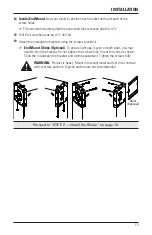
Page 9: ...ously made marks then mark each of the screw holes Drill the screw holes using a 1 8 drill bit WARNING Product is heavy Mount into wood metal studs or into concrete with concrete anchors Drywall anchors are not recommended Use a level to check that the mounting surface is level Shim the brackets if necessary Attach the installation brackets using the screws provided End Mount Shims Optional To ens...

Page 10: ...uired to mount the brackets The top of the installation brackets should be at the desired height of the shade Drill the screw holes using a 1 8 drill bit Use a level to check that the mounting surface is level Shim the brackets if necessary Attach the installation brackets using the screws provided WARNING Product is heavy Mount into wood metal studs or into concrete with concrete anchors Drywall ...

Page 11: ...nce the first intermediate bracket mark when measuring and marking for the next intermediate brackets After the last intermediate bracket is marked the distance from that bracket to the idle end window jamb should be the end panel ordered width Place the outside edges of the brackets on the previously made marks then mark each of the screw holes Drill the screw holes using a 1 8 drill bit WARNING ...

Page 12: ...Covers If Ordered If you ordered bracket covers Install the bracket covers by aligning the bracket cover channels with the bracket and sliding it onto the bracket Proceed to STEP 2 Install the Shade on page 15 Bracket Cover Bracket Cover ...

Page 13: ... on the previously made mark s A minimum 3 flat vertical surface is required to mount the installation brackets The top of the installation brackets should be at the desired height of the shade Drill the screw holes using a 1 8 drill bit Use a level to check that the mounting surface is level Shim the brackets if necessary Be sure all the intermediate brackets are mounted so they face the motor br...

Page 14: ...en the brackets and the mounting surface For Outside Mount Use a pencil to mark the bottom and outside edges of the brackets on the mounting surface For Inside Mount Use a pencil to mark the outside edges of the brackets on the mounting surface Remove the assembly from the window Remove the brackets from the fascia panel Outside Mount Use your marks to position each bracket and mark each of the sc...

Page 15: ...s using the screws provided End Mount Shims Optional To ensure light gap is even on both sides you may need to shim the bracket Do not tighten the screws fully Orient the shim as shown Slide the in between the bracket and window casement Tighten the screws fully WARNING Product is heavy Mount into wood metal studs or into concrete with concrete anchors Drywall anchors are not recommended Proceed t...

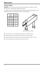
Page 16: ...he width of the shade as shown in the table below Locate the studs or other substantial material for your mounting surface Mark the pocket for the locations you have chosen for the screw holes Drill the screw holes into the pocket and the mounting surface using a 1 8 drill bit Fasten the pocket to the mounting surface using the screws Shade Width Screws Required Up to 36 4 361 8 66 6 661 8 90 8 90...

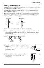
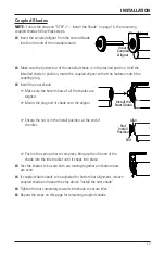
Page 17: ...per banding in place The bottom bar should be positioned just below the fabric in either the standard or reverse roll position based on your order Ensure the nut is in the install position at the end of the idler CAUTION Do not install motor end first idle end must be installed first Do not rotate the motor in the tube manually it will damage the motor Push idle end of shade into the hole of the i...

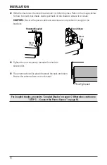
Page 18: ...power cable and antenna are not pinched or caught in the brackets Tighten the nut completely towards the shade to secure idler The antenna should be placed towards the back and down Ensure the antenna does not touch metal For Coupled shades proceed to Coupled Shades on page 17 Otherwise continue to STEP 3 Connect the Power Source on page 18 Motor End Fascia Shade Motor End Standard Coupled Shade N...

Page 19: ... all the shades are aligned Mount the plug end of shade onto the aligner Ensure the nut is in the install position at the end of the idler Push in the spring idler to compress Bring up the idle end of the shade into the idle bracket until it snaps into place Test the shades to be sure both are running together and bottom bars are even If coupled shade needs to be adjusted for bottom bar alignment ...

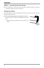
Page 20: ...ring to 120V power Testing the Shade Testing the shade with the programming button will allow you to ensure the motor and power source are working correctly Press the programming button the black button located on the bottom or top of the motor end depending on your shade type Press the button to alternately lower stop and raise the shade Programming Button ...

Page 21: ...hts blink approximately 6 seconds The remote is now in programming mode 2 Press desired group number 1 6 on the remote The backlit group number will flash to show it is selected 3 While pressing the programming button on the shade press OPEN on the remote The green light flashes once and the shade will move slightly to indicate that it has joined the group Release the programming button 4 Press an...

Page 22: ...ion and Programming Information PowerView Pebble Remote and or PowerView Surface Remote Operation For information regarding operation and programming of the PowerView remote refer to your PowerView Automation Remote Control Guide or to the online PowerView Step by Step Guide at hunterdouglas com operating systems motorized powerview motorization manuals PowerView Scene Controller For information r...

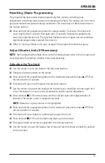
Page 23: ...its need adjusting Adjusting the Top Limit Use the remote to raise the shade to the fully open position Deselect all group numbers on the remote Press and hold the programming button on the shade and press and release OPEN on the remote within 4 seconds The shade will jog to confirm upper limit has been cleared Use the remote to position the shade at the top where you would like the new upper limi...

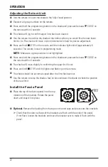
Page 24: ... not highlighted Press and hold the programming button on the shade and press and release CLOSE on the remote within 4 seconds The shade will move slightly to confirming the upper limit is set Press and hold STOP until the lights stop flashing on the remote The shade should run at normal speed after the limit has been set Use the remote to raise the shade a few inches and lower the shade to check ...

Page 25: ...on brackets Solution Check that the installation brackets are aligned and level Check that the roller tube is completely inserted into the installation brackets See STEP 2 Install the Shade on page 15 Bracket shades only Check to ensure the bracket distance is correct If the brackets are mounted too closely to one another the shade will not operate correctly Fascia shade only If the tab on the fas...

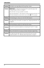
Page 26: ...should come on when STOP is pressed Problem The shade hangs too high or too low when fully lowered Solution The shades lower limit needs to be adjusted see Adjusting the Bottom Limit on page 22 Problem The shade hangs too high or too low when fully raised Solution The top limit needs to be adjusted see Adjusting the Top Limit on page 21 Problem Remove the shade from all groups and erase the shade ...

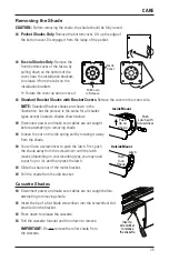
Page 27: ...t caught before attempting to removing shade Loosen the nut on the idle spring end by rotating it away from the shade You will use a screwdriver to push the latch First push the shade away from the screwdriver until the latch moves depending on your mounting type you may need to push up or in and then press the latch Slide the shade out of the motor bracket Pull the shade from the idle bracket Cas...

Page 28: ... with low suction for more thorough dust removal Compressed Air Hair Dryer Cool Setting Use compressed air or a hair dryer on a cool setting to blow dust and dirt off of shades Spot Cleaning CAUTION Do not spot clean Alustra Woven Textures fabrics Fiji and Fiji Dimout fabrics Prepare a solution of warm water and a mild detergent Dampen a clean cloth in the solution and wring it out Dab the spot wi...

Page 29: ...uipment This equipment complies with FCC radiation exposure limits set forth for an uncontrolled environment and meets the FCC radio frequency RF Exposure Guidelines This equipment should be installed and operated keeping the radiator at least 20 cm or more away from person s body RF Exposure requirements are met when installed in mobile equipment This module cannot be installed in portable equipm...

Page 30: ...las Europe B V Piekstraat 2 3071 EL Rotterdam The Netherlands certify and declare under our sole responsibility that assemblies PV4 conform with the essential requirements of the EMC directive 2004 108 EC and R TTE directive 1999 5 EC A copy of the original declaration of conformity may be found at www hunterdouglas com RFcertifications ...

Page 31: ......

Page 32: ...ts are covered for 5 years from the date of purchase 1 Contact your original dealer place of purchase for warranty assistance 2 Visit hunterdouglas com for additional warranty information frequently asked questions and access to service locations 3 Contact Hunter Douglas at 888 501 8364 for technical support certain parts free of charge for assistance in obtaining warranty service or for further e...

Reviews: