INSTALLATION
28
Step H. Attach the Optional Valance
IMPORTANT:
Two valances are available, the Bypass Standard Valance (3
1
/
2
") and the
Decorative Valance (5"). Both are mounted in a similar manner.
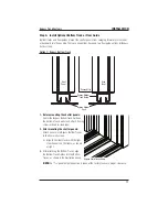
1.
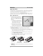
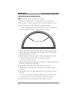
Attach the valance returns.
➤
Remove tabs from corner keys as described on page 4.
➤
Apply a small amount of instant adhesive or contact cement to inside of mitered corners
of valance.
➤
Insert the corner key into the end of the valance and hold firmly until set.
➤
Glue and attach the valance returns.
2.
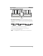
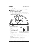
The supplied valance clips will correctly position either valance to conceal the tracks and
carriers.
3.
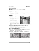
Align the valance clips with the pre-drilled installation holes on the face of the Bypass Frame,
and secure with the supplied #8 x 1" Truss Head screws.
NOTE:
Valance clips should be mounted with the clear plastic insert facing outward, and
the release button pointing downward, as shown in the photo below. The valance clip mount
allows for a
3
/
16
" height adjustment if needed. To adjust, loosen the screw slightly, slide the
valance clip up or down to desired position, then re-tighten the screw.
4.
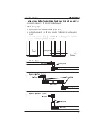
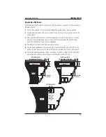
Position the valance so that the groove on the back is “hooked” over the catch on the tops of
the valance clips, then “rock” the valance downward until the valance clicks into place.
NOTE:
The Decorative Valance has two grooves on the back. The top groove should be used
for Bypass Track Frame installations in order to conceal the tracks and carriers.
5.
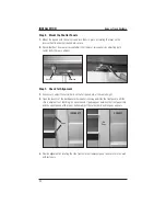
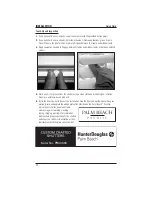
If you need to remove the valance after installation, for each of the installed valance clips,
reach up under the bottom of the valance and locate the clip, then press upward on the
spring-loaded valance clip release button (shown below left), and “rock” the bottom of the
valance outward to release.
Step I. Complete the Installation
■
Perform any necessary finish work to complete the installation (see page 42).
Bypass Track Systems

