23
Procedure:
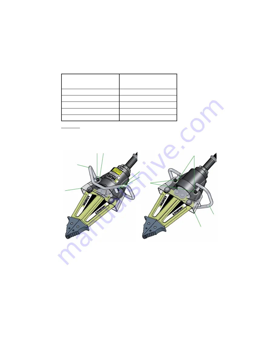
1. Close the rescue unit until a gap of only a few mm /
in.
remains between the tips.
Disconnect the device from the hydraulic power supply unit and clean thoroughly.
2. Unscrew nuts ‘A’, remove washers ‘B’ and remove fi xing bolts ‘C’.
3. Pull the handle ‘D’ backwards over the hose connections.
4. In the same way, pull the protective cover “E” backwards over the hose connections.
A
C
D
B
10.3.2 Spreader arm, spreader tips, protection cover and handle replacement
E
Components to be
replaced
Required work steps
Handle
1. - 3. and 7.
Protective cover
1. - 4. and 7.
Plug-on tips
1. - 5. and 7.
Lever links
1. - 5. and 7.
Spreader arms
1. - 6. and 7.
B
C
B
D
E


