background image

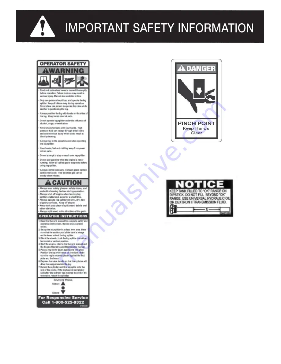
PART NUMBER: 51018900
LOCATION: TOP OF HYDRAULIC CYLINDER

PART NUMBER: 52023200
LOCATION: HYDRAULIC TANK
LOWER TANK, RIGHT CORNER

PART NUMBER: 52055200
LOCATION: BOTH STRIPPER
PLATES AND CYLINDER

Page 2

Summary of Contents for 1032822

Page 1: ...symbol identifies important safety messages in this manual Failure to follow this important safety information may result in serious injury or death LS125 810 0310 Rev 2 MODEL NO 1032822 1032830 Owner...

Page 2: ...4 Repair and Maintenance Safety 4 Hydraulic Safety 5 Fire Prevention 5 6 Towing Safety 6 Assembly Instructions 7 9 Operating Instructions 11 12 Engine Oil Recommendations 11 Hydraulic Oil Recommendati...

Page 3: ...splitting wood It is designed for this use only Any other use can cause serious injury or death PEPER PERPERSONALSONAL PROTECTIVE EQUIPMENT BEFORE operating this log splitter make sure that you wear...

Page 4: ...PART NUMBER 51018900 LOCATION TOP OF HYDRAULIC CYLINDER PART NUMBER 52023200 LOCATION HYDRAULIC TANK LOWER TANK RIGHT CORNER PART NUMBER 52055200 LOCATION BOTH STRIPPER PLATES AND CYLINDER Page 2...

Page 5: ...slope could cause the log splitter to roll over or logs to fall off NEVER operate your log splitter in an enclosed area Exhaust fumes contain carbon monoxide which can be deadly when inhaled NEVER at...

Page 6: ...ith the muffler and other hot areas of the engine during operation or after running to prevent burns REPAIR AND MAINTENANCE SAFETY NEVER operate your log splitter when it is in poor mechanical conditi...

Page 7: ...hydraulic valve The pressure relief valve on your log splitter is preset at the factory Only a qualified service technician should perform this adjustment FIRE PREVENTION NEVER operate your log splitt...

Page 8: ...plitter ALWAYS check before towing to make sure that the log splitter is correctly and securely attached to the towing vehicle and that the safety chains are secured to the hitch or bumper of the vehi...

Page 9: ...h piece for shipping damage If any part is damaged contact your dealer or delivering carrier STEP 2 Attach the two wheels 2 to the tank assembly 1 wheel spindles using the 3 4 light flat washers 3 3 4...

Page 10: ...available through hardware and farm stores ITEM NO PART NO DESCRIPTION QTY 1 401613R0 BeamAssembly 1 2 071022WC PivotPin 1 3 O L 1 2 3 4 R Clip Pin 1 O L Obtain locally Common fasteners available thr...

Page 11: ...olt 1 3 O L 5 16 x 1 GR5 Hex Bolt 4 4 O L 5 16 x 1 1 2 GR5 Hex Bolt 2 5 39024600 1 2 x 44 Hydraulic Pressure Hose 1 6 39025200 44 Return Hose 1 7 39026800 3 4 x 12 Suction Hose 1 8 39032000 3 4 NPT x...

Page 12: ...in with Hook 2 BEAM ASSEMBLY BREAKDOWN ITEM NO PART NO DESCRIPTION QTY 1 O L 1 2 X 3 1 4 GR 5 Hex Cap Bolt 1 2 O L 1 2 Regular Lock Washer 1 3 O L 1 2 Hex Nut 1 4 401414R0 Beam 1 5 40141700 Wedge 1 6...

Page 13: ...s approximately 5 8 quart 20 ounces 0 6 liter STEP 2 After the hydraulic reservoir and the engine crankcase are filled with oil start the engine The hydraulic pump should prime itself With the engine...

Page 14: ...PORTANT TO EXTEND THE LIFE OF THE HYDRAULIC CYLINDER AVOID BOTTOMING OUT WEDGE PLATE TO THE FOOT PIECE TO CONFORM WITH INDUSTRY SAFETY RECOMMENDATIONS THE WEDGE STOPS 1 5 INCHES FROM THE END OF THE ST...

Page 15: ...e manufacturer reserve the right to change the product and or specifications in this manual without notification The manual is for information usage only and the pictures and drawings depicted herein...

Page 16: ...u e n P 8 X 0 8 4 s m i R n o E G D E W s g n i W r e d a e r p S h t i w h g i H 7 E Z I S M A E B 6 X 6 C I L U A R D Y H L A T O T Y T I C A P A C s n o l l a G 5 R E T L I F e l b a e c a l p e R...

Reviews: