14
FASTENERS
Inspect all bolts and nuts for tightness. Tighten as required. (Refer to Table 4, Page 15)
Replace all missing or damaged fasteners before operating the hammer.
Fastener bolt and nut sizes are listed in Table 3. These are wrench sizes (distance across
flats.)
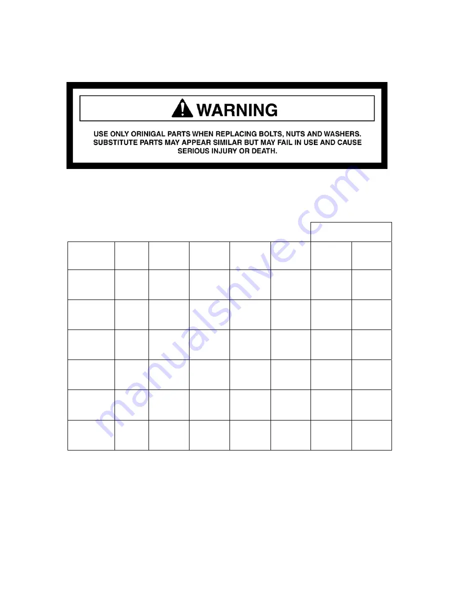
Table 3. Bolt Sizes
GAS VALVE
HAMMER
NIPPLES
(mm.)
BRACKET
BOLTS
(mm.)
SIDE ROD
BACK NUT
(mm.)
SIDE ROD
ALLEN
HEAD
(mm.)
LIFTING
EYES
(inches)
CAP
(inches)
BODY
(mm.)
HH100 19 28 NA *14
½”-13pt
1” Crow
Foot
36
HH150-2 30
36
32
NA ½”-13pt
1” Crow
Foot
36
HH300-2 30
36
41
NA ½”-13pt
1” Crow
Foot
36
HH500-2
30 36 41 14
¾”-10pt
1” Crow
Foot
36
HH750-2
30 36 46 14
¾”-10pt
1” Crow
Foot
36
HH1000-2
36 50 46 17
¾”-10pt
1” Crow
Foot
36
* Allen wrench size for the front and back cap bolts.
Summary of Contents for HH100
Page 1: ...HUSKIE HYDRAULIC HAMMERS SERVICE MANUAL HH100 HH150 2 HH300 2 HH500 2 HH750 2 HH1000 2 ...
Page 2: ...2 ...
Page 33: ...33 9 PARTS LIST AND ILLUSTRATIONS HH100 HH150 2 HH300 2 HH500 2 HH750 2 HH1000 2 ...
Page 35: ...35 HH100 HAMMER Effective 07 09 ...
Page 37: ...37 ...
Page 39: ...39 HH150 2 HAMMER S N 001 099 2B2 1000 UP Effective 07 09 ...
Page 41: ...41 ...
Page 43: ...43 HH300 2 HAMMER S N 001 099 2E2 1000 UP Effective 07 09 ...
Page 47: ......
Page 49: ...49 HH500 2 HAMMER S N 001 099 2R2 1000 UP Effective 07 09 ...
Page 55: ...55 HH750 2 HAMMER S N 001 099 2F2 1000 UP Effective 07 09 ...
Page 59: ...59 ...
Page 61: ...61 Effective 07 09 HH1000 2 HAMMER S N 001 099 2H2 1000 UP ...


