background image

http://www.huskietools.com

info@huskietools.com

7

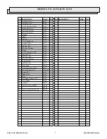
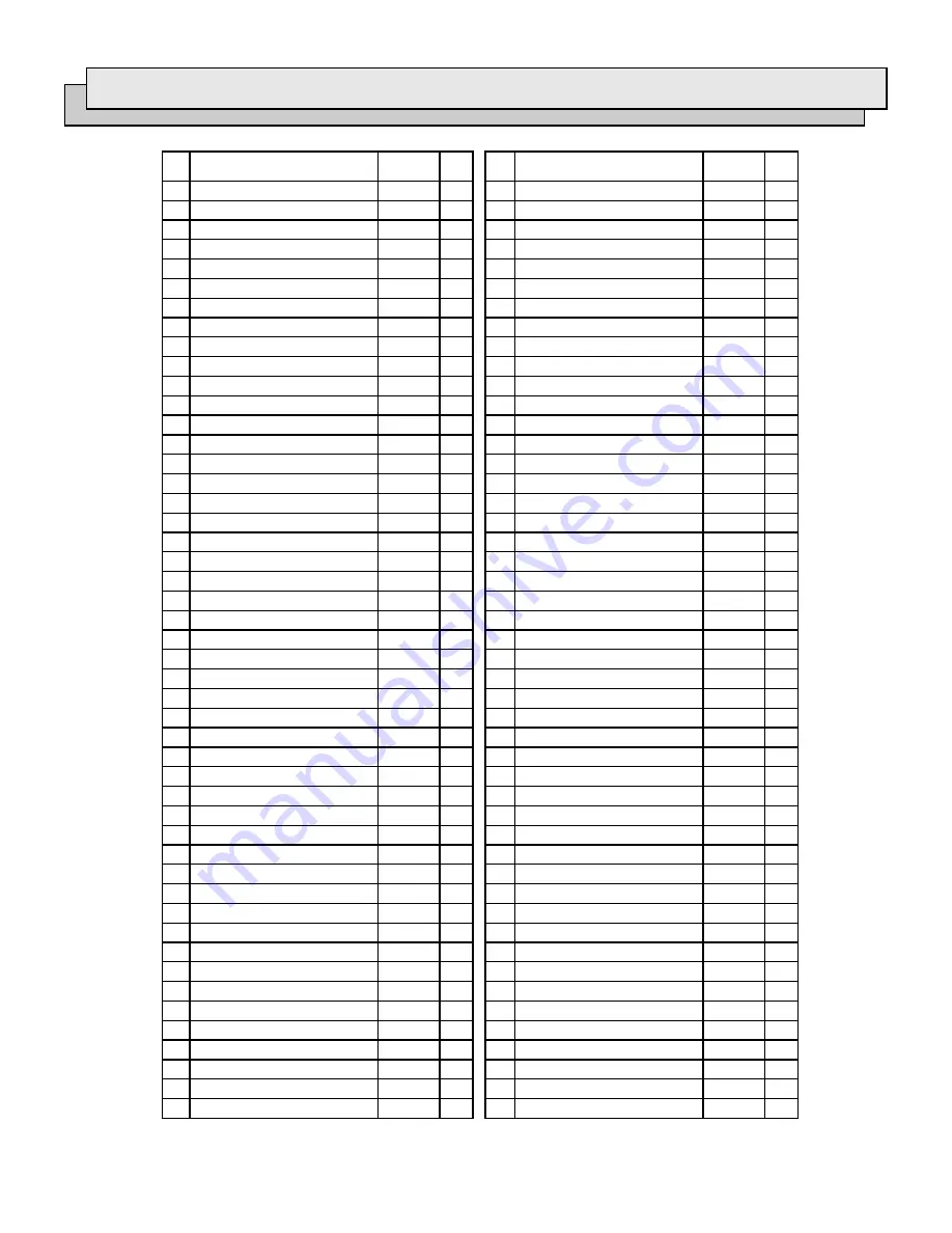
M O D E L S P - 4 0   PA RT S   L I S T

 Guide Piece (A) 

40-02

     1 

 Guide Piece (B) 

40-04

     1 

 3 X 12 Drive Pin (AW) 

40-05

     2 

 Head Shear (H.A.) 

40-07H

     1 

 M12 Lock Washer 

40-09

     2 

 M12 X 30 Screw 

40-11

     2 

 Bushing 

40-12

     2 

 Blade 

40-14

     1 

 Pin (43) 

40-15

     1 

10   CE-10 Snap Ring 

40-16

     2 

11   Lock Pin Ass'y 

40-17

     1 

12   M8 Hex. Nut 

40-24

     4 

13   M8 Lock Washer 

40-25

     4 

14   Roller 

40-27

     2 

15   4 X 40 Drive Pin (AW) 

40-28

     1 

16   Stud Bolt (17) 

40-30

     2 

17   M10 Hex. Nut 

40-31

     4 

18   M10 Lock Washer 

40-32

     4 

19   Support Plate 

40-34

     2 

20   Stud Bolt (16) 

40-36

     2 

21   Body Head 

P40-02

     1 

22   2 X 12 Drive Pin (AW) 

40-21

     1 

23   M5 X 8 Screw (C.P.) 

P55A-02      1 

24   Spring (121) 

40-38

     1 

25   Blade Screw 

40-40

     1 

26   Ram 

40-42

     1 

27   P-32 Back Up Ring (B.C.) 

40-43

     1 

28   P-32 O-Ring 

40-44

     1 

29   Cylinder 

P40-01

     1 

30   Female Coupler IZUMI 

100-24

     1 

31  F. 

P85-80

     1 

32   Female Coupler P.H. Type 

P85-81

     1 

DESCRIPTION

QTY.

CODE

QTY.

NO.

CODE

NO. DESCRIPTION

Summary of Contents for SP-40

Page 1: ...HUSKIE TOOLS INC Operating Instruction Manual For SP 40 Hydraulic Cutters With Parts List...

Page 2: ......

Page 3: ...erating without problems 5 The most common problem encountered is blade breakage Ninety nine percent of all breakage occurs because the cutter head is not securely latched before cutting If the latch...

Page 4: ...carrying bag to protect them from sand and dirt Extra bags can be purchased 11 Always carry a spare blade preferably attached to the carrying bag 12 Use clear hydraulic fluid MV 32 available from you...

Page 5: ...ssure with no load and the release lever seems to be stuck Solution A Use both hands to depress lever using body weight and the ground or other strong surface for support If this does not work proceed...

Page 6: ...to the blade This will ensure a proper cut with minimal distortion If the material is cut at any other angle severe blade damage may occur Refer to diagram on page two for proper alignment 7 Proceed...

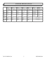
Page 7: ...5 Lx3 W size 11 Lx3 5 W size 14 Lx3 25 W size 12 Lx4 W size 15 Lx4 5 W size 19 Lx5 W size 24 Lx6 W Wire 20mm 22mm 32mm Do not cut 26mm Communication 100mm Ropes 9 16 7 8 1 1 4 1 cables 3 35 4 Soft Ste...

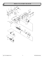
Page 8: ...http www huskietools com info huskietools com 6 MODEL SP 40 PARTS DIAGRAM...

Page 9: ...4 13 M8 Lock Washer 40 25 4 14 Roller 40 27 2 15 4 X 40 Drive Pin AW 40 28 1 16 Stud Bolt 17 40 30 2 17 M10 Hex Nut 40 31 4 18 M10 Lock Washer 40 32 4 19 Support Plate 40 34 2 20 Stud Bolt 16 40 36 2...

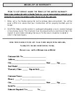
Page 10: ...ear warranty on parts and labor REPAIR AND WARRANTY CLAIMS All claims must be sent to Huskie for inspection and authorization A Return Goods Authorization is required before shipping tools to Huskie S...

Page 11: ...and we recommend that it be insured A cover letter indicating the reason for the return should be included in order to facilitate repairs SEND THIS PORTION WITH ANY TOOL WHEN REQUESTING REPAIRS WARRA...

Page 12: ...198 N Brandon Drive Glendale Heights Illinois 60139 630 893 7755 Fax 800 345 3767 Toll Free 1 800 860 6170 http www huskietools com info huskietools com...

Reviews: