background image


M

O

C

.

S

L

O

O

T

Y

K

S

U

H


.

e

c

n

a

t

s

i

s

s

a


r

e

h

t

r

u

f


r

o

f


Y

K

S

U

H

-

D

H

-

8

8

8

-

1


t

c

a

t

n

o

c


e

s

a

e

l

P


Troubleshooting 


Problem 

Possible Cause

Solution 

There is low pressure, not
enough air, or the
compressor does not stop.

The tank drain valve is open.
There is a leak in the fittings.

There is a prolonged orexcessive 
use of air.
The compressor is not large
enough.

There is a hole in the air hose.
The tank leaks.

The seals are blown.
The valve leaks.
There is a leaking or worn piston.

Close the drain valve.
Check fittings with soapy water. Tighten or reseal leaking
fittings DO NOT OVERTIGHTEN.
Decrease the amount of air used.
Check the air requirement of the accessory. If it is higher 
than the CFM and the pressure supplied by the compressor, 
you need a larger compressor. Most accessories are rated 
at 25% of the actual CFM while running continuously.
Check and replace if necessary.
                            Immediately replace the tank. DO NOT 
attempt to repair.
Replace the compressor assembly.

Air leaks from theregulator 
or the regulator does not
regulate air pressure.

The internal parts of the regulator 
are dirty or damaged.

Replace the regulator or internal parts.

The regulated pressure 
gauge reading drops when
the air accessory is being 
used.

This is normal.

The compressor is not large 
enough.

If the pressure drops too low, adjust the regulator while 
the accessory is used.

Check the air requirement of the accessory. If it is higher 
than the CFM and the pressure supplied bythe compressor, 
you need a larger compressor. Most accessories are rated 
at 25% of the actual CFM while running continuously.

The pressure relief valve 
opens.

The tank pressure exceeds the
normal rating pressure.
The pressure switch is stuck.

Replace the pressure switch.

Replace the pressure switch.

The motor will not run.

Tank pressure exceeds the
preset pressure switch limit.
The fuse is blown or the circuit
breaker tripped.

The check valve is stuck in the
open position.
The wire gauge in the cord is
wrong or the extension cord
length is excessive.
There are loose electrical
connections.
The motor’s thermal overload
protection has tripped.

The motor, capacitor or safety
valve is defective.

The motor will start automatically when the tank pressure 
drops below the tank cut-in pressure.

Have the compressor serviced by a qualified technician.

Turn the air compressor off, unplug the power cord and 
wait until the motor has cooled down. Plug in the power 
cord only after the motor has cooled down, waiting at least
five minutes to make sure the thermal overload protector 
has recovered.

Check for proper gauge and extension cord length.

Contact an authorized service center.

Remove and clean or replace.

Replace the blown fuse or reset the circuit breaker. Do not 
use a fuse or circuit breaker with a higher rating than 
specified for your branch circuit. Check for proper fuse; 
type T fuse is acceptable. Check for low voltage and proper
extension cord size. Disconnect other applications from
the circuit. Operate the compressor on a dedicated circuit.


WARNING: 

12

Summary of Contents for 0300813A

Page 1: ...ducts designed to enhance your home Visit us online to see our full line of products available for your home improvement needs Thank you for choosing Husky USE AND CARE GUIDE 8 GALLON HOTDOG OIL FREE...

Page 2: ...is necessary to properly lter and purify the air to meet minimal speci cations for Grade D breathing as described in Compressed Gas Association Commodity Speci cation G 7 1 1966 OSHA 29 CF9 1910 134 C...

Page 3: ...ressor to spray chemicals Your lungs can be damaged by inhaling toxic fumes A respirator may be necessary in dusty environments or when spraying paint 15 Do not use this compressor if any parts have b...

Page 4: ...heavy enough for a short distance will be too light for a greater distance A line that can support one power tool may not be able to support two or three tools ELECTRICAL SAFETY GROUNDING INSTRUCTIONS...

Page 5: ...han those specifically stated in this warranty ADDITIONAL LIMITATIONS To the extent permitted by applicable law all implied warranties including warranties of merchantability or fitness for a particul...

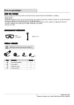
Page 6: ...ndle F 2 Thumbscrews C 25 coil air hose quick coupler female quick plug male quick plugs 2 blow gun tire chuck high pressure nozzle inflation needles 2 adaptor sealant tape Instruction manual TOOLS RE...

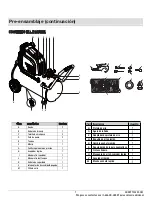
Page 7: ...mbscrews C 2 Rubber foot D 1 k n a T E 1 1 1 1 1 Handle F G Pressure regulator knob H Quick coupler I Regulator pressure gauge 1 Tank pressure gauge J 1 Safety valve K h c t i w S F F O N O L 1 Air lt...

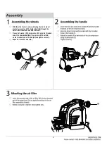
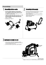
Page 8: ...mble a M10 shoulder bolt AA through the holes in the wheel and tank wheel bracket Place a at washer DD lock washer CC onto the threaded end of the shoulder bolt AA Then place a M10 nut BB on the threa...

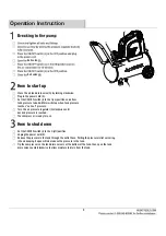
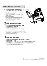
Page 9: ...regulator G clockwise until desired pressure is reached The compressor is ready for use How to shut down Set the ON OFF switch I to the O off position Unplug the power cord X Reduce the pressure in th...

Page 10: ...Ball valve Ball valve Ball valve Ball valve Ball valve Ball valve Maintenance 10...

Page 11: ...N connect it directly to the air hose U pre attached If using the inflation needle 0 pre attached connect it directly to the blow gun N If using the high pressure nozzle Q connect it directly to the b...

Page 12: ...requirement of the accessory If it is higher than the CFM and the pressure supplied bythe compressor you need a larger compressor Most accessories are rated at 25 of the actual CFM while running conti...

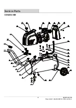
Page 13: ...3 1 Service Parts EXPLODED VIEW M O C S L O O T Y K S U H e c n a t s i s s a r e h t r u f r o f Y K S U H D H 8 8 8 1 t c a t n o c e s a e l P...

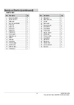
Page 14: ...ut 6 7 Power cord 1 1 1 8 Check valve 9 Thumbscrew Quick coupler 0 1 Regulator assy 1 1 12 Handle 13 Handgrip 14 Safety valve 1 2 15 Pressure gauge e l u r r e f h c t i w S 6 1 ON OFF switch 7 1 18 F...

Page 15: ...ions problems missing parts Before returning to the store call Husky Customer Service 8 a m 7 p m EST Monday Friday 9 a m 6 p m EST Saturday 1 888 HD HUSKY HUSKYTOOLS COM Retain this manual for future...

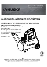
Page 16: ...n Visitez nous en ligne pour voir notre gamme compl te de produits disponibles pour vos besoins de r novation Merci d avoir choisi Husky GUIDE D UTILISATION ET D ENTRETIEN COMPRESSEUR D AIR HOT DOG 8...

Page 17: ...as especi caciones m nimas para respiraci n Grado D como se describe en Especi caciones para Art culos de la Asociaci n de Gas comprimido G 7 1 1966 OSHA 29 CF9 1910 134 Compressed Gas Association 422...

Page 18: ...den resultar da ados al inhalar humos t xicos Puede ser necesario un respirador en ambientes de mucho polvo o cuando roc e pintura 15 No use este compresor si alguna parte ha estado expuesta al agua S...

Page 19: ...n cable su cientemente fuerte para una distancia corta ser muy ligero para una distancia mayor Una l nea que puede soportar una herramienta el ctrica puede no ser capaz de soportar dos o tres herramie...

Page 20: ...ficamente en esta garant a LIMITACIONES ADICIONALES En la medida permitida por la ley aplicable todas las garant as impl citas incluyendo garant as de comercializaci n o idoneidad para un prop sito p...

Page 21: ...pidos macho 2 pistola de aire comprimido la tirada de los neum ticos la boquilla de alta presi n agujas de in aci n 2 adaptador cinta selladora Manual de instrucciones samblaje de la manija incluye 1...

Page 22: ...i n H o d i p r r o d a l p o c A I r o d a l u g e r o r t e m n a M J e u q n a t l e d o r t e m n a M K d a d i r u g e s e d a l u v l V L M F Interruptor de Encendido Apagado Cantidad 2 1 2 2 1...

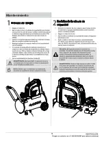
Page 23: ...no de resalto de M10 AA a trav s de los agujeros en la rueda y el soporte de la rueda del tanque Coloque una arandelas planas dd arandela CC en el extremo roscado del tornillo de hombro AA Luego coloq...

Page 24: ...oj hasta que se alcance la presi n deseada El compresor est listo para usarse C MO DESCONECTARLA Coloque el interruptor de ENCENDIDO APAGADO I en la posici n O apagado Desenchufe el cable el ctrico X...

Page 25: ...10 Mantenimiento...

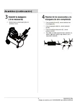
Page 26: ...R R H 11 Asamblea continuaci n Si se utiliza un mandril neum tico S conectarlo a un enchufe r pido macho W y luego conectar con el acoplamiento r pido V R w...

Page 27: ...istrada por el compresor necesitar un compresor m s grande La mayor a de los accesorios est n clasi cados para el 25 de los m3 min reales que se utilizan durante el funcionamiento continuo La v lvula...

Page 28: ...3 1 Piezas de servicio VISTA ESQUEM TICA M O C S L O O T Y K S U H l a n o i c i d a a i c n e t s i s a a r a p Y K S U H D H 8 8 8 1 l e n o c o t c a t n o c n e e s a g n P...

Page 29: ...alimentaci n 1 1 1 8 V lvula de retenci n 9 Tornillo de mariposa Acoplador r pido 0 1 Regulador 1 1 12 Manija 13 Agarre de la manija 14 V lvula de drenaje 1 2 15 Man metro a l o r i V 6 1 Interruptor...

Page 30: ...iezas Antes de regresar a la tienda llame a Servicio al Cliente de Husky de 8 a m a 7 p m hora local del Este de lunes a viernes 9 a m a 6 p m hora local del Este s bado 1 888 HD HUSKY HUSKYTOOLS COM...

Reviews: