background image

 19 

HUSKYTOOLS.COM


Please contact 1-888-43-HUSKY for further assistance.

Maintenance

GENERAL MAINTENACE

All repairs should be performed by an authorized service representative.

WARNING:

 Disconnect, tag, and lock out the power 

source, and then release all pressure from the system 
before attempting to install, service, relocate, or perform 
any maintenance.

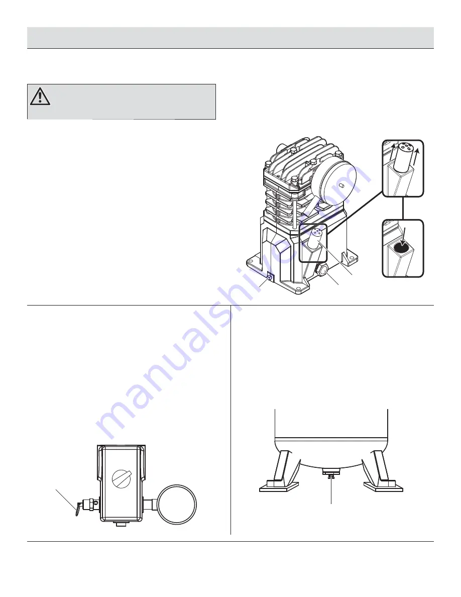
Checking and changing the oil

Maintain the proper oil level by checking the oil sight glass (1) 
daily. Change the oil in the pump every 3 months. Use the following 
procedure to change (or add) oil.


Run the compressor for ten minutes to warm up the oil if the 
unit has not been in use for an extended period of time.


Turn the compressor off and disconnect the compressor 
from the power source.


Position a pan under the pump drain plug (2) to catch the oil.


Remove the pump drain plug (2) and allow the oil to collect 
in the pan.


Reinsert the oil drain plug. Remove the breather (3) from the 
pump. Pour new, unused oil into the pump. Do not overfi ll.


Reinsert the breather (3) into position. Return power to the 
compressor for use.

Checking the ASME safety valve


Run the air compressor until it reaches cut-out pressure.


Turn the compressor off and disconnect the compressor 
from the power source.


Put on safety glasses. Protect yourself from fast moving air.


Pull on the ring of the ASME safety valve (1). This 
releases pressure from the tank. The safety valve should 
automatically close at approximately 40 - 50 psi.

If the safety valve does not allow air to be released when you 
pull on the ring, or if it does not close automatically, it MUST be 
replaced.

Draining the tank of moisture


Turn the compressor off and disconnect it from the power 
source.


Release the pressure from the compressor by pulling on 
the ASME safety valve. The ASME safety valve should close 
at approximately 40 - 50 psi.


Open the drain valve (1) underneath the tank. Remaining 
air pressure will assist in removing moisture from the tank.

2

1

3

1

1

Summary of Contents for 1000710098

Page 1: ...enhance your home Visit us online to see our full line of products available for your home improvement needs Thank you for choosing Husky USE AND CARE GUIDE 60 GALLON STATIONARY AIR COMPRESSOR Questi...

Page 2: ...ntly hazardous situation which if not avoided WILL result in death or serious injury WARNING Indicates a potentially hazardous situation which if not avoided COULD result in death or serious injury CA...

Page 3: ...he tank resulting in damage from rupture or explosion Always replace worn cracked or damaged tanks CAUTION See the compressor specification decal for maximum operating pressure Do not operate with pre...

Page 4: ...not recommended for use with this compressor Alterations and or modifications are a form of misuse which could result in a hazardous condition leading to possible personal injury or equipment damage...

Page 5: ...l and local electrical codes 1 Follow all local electrical and safety codes as well as in the United States the National Electrical Codes NEC and Occupational Safety and Health Act OSHA 2 Avoid body c...

Page 6: ...or expense that may result from any defect failure or malfunction of the manufacturer s product is not covered by this warranty Some states do not allow the exclusion or limitations of incidental or...

Page 7: ...a minimum clearance of 18 in between the compressor flywheel or fan and the wall and ensure clear access to the drain valve to facilitate condensate drainage Do not locate the compressor air inlet ne...

Page 8: ...8 Pre Installation PACKAGE CONTENTS Part Description Quantity A Air Compressor Unit 1 B Air Filter Assembly 1 A B...

Page 9: ...sure from the discharge tube and allows the compressor to restart easier B ASME Safety Valve This valve automatically releases air if the tank pressure exceeds the preset maximum C Discharge Tube This...

Page 10: ...tlet Size 3 4 NPT Number of Cylinders 2 Oil Capacity approximately 8 5 ounces Voltage 230 240 Volts 15 Amps Length 20 in 60 Hz 1 Phase Width 20 in Air Delivery 90 psi 10 2 SCFM Height 66 5 in Air Deli...

Page 11: ...s to the drain valve to facilitate condensate drainage IMPORTANT It is extremely important to install the compressor in a clean well ventilated area where the surrounding air temperature will not be m...

Page 12: ...onry bit Holes drilled must be at least as deep as the concrete wedge anchors being used 3 Inserting the mounting bolts Insert the mounting bolts into the drilled holes Place a washer on each bolt Thr...

Page 13: ...outlet For units that do not have a factory installed cord install permanent wiring from the electrical source to the pressure switch with a ground conductor connected to the grounding screw on the pr...

Page 14: ...l 2 line terminal 3 ground screw 4 and ground line 5 3 Making the electrical connections Remove the ground screw 1 Install the strain relief on the pressure switch 2 Do not tighten the strain relief o...

Page 15: ...screwdriver with a hammer until tight Tighten the strain relief screws 2 to hold the power cord securely 5 Reinstalling the pressure switch cover Replace the pressure switch cover The knob must be in...

Page 16: ...ife of the unit you will clean or replace the filter as needed This air compressor unit can be installed as part of an air distribution system Any tube pipe or hose used in an air distribution system...

Page 17: ...n the pump to determine the oil level Add oil to the pump if the oil level is low 2 2 Starting up and breaking in the compressor WARNING Do not attach air tools to the open end of the hose until start...

Page 18: ...0 50 psi Do not operate the drain with more than 40 psi in the tank or the drain valve may be damaged Drain the tank of moisture daily using the drain valve at the bottom of the tank IMPORTANT This co...

Page 19: ...insert the oil drain plug Remove the breather 3 from the pump Pour new unused oil into the pump Do not overfill Reinsert the breather 3 into position Return power to the compressor for use 2 Checking...

Page 20: ...do not remove the four bolts 1 holding the motor in place Shift the motor towards the pump The belt should be slack and easily removed Replace the belt Move the motor back to the original position to...

Page 21: ...all service relocate or perform any maintenance Operation Daily Weekly Monthly Every 3 Months Check Oil Level X Drain Tank X Check Air Filter X Check Safety Valve X Clean Unit X Check Belt Tension X C...

Page 22: ...l more frequently The piston pin bores are worn Remove the piston assemblies from the compressor and inspect for excess wear Replace the excessively worn piston pin or pistons as required Maintain the...

Page 23: ...is restricted Clean or replace the air filter element The electrical connections are loose Check all the electrical connections The pressure switch shut off pressure is set too high Replace the pressu...

Page 24: ...24 Service Parts Compressor MODEL VT631404 3 4 27 28 25 29 32 33 31 30 26 34 21 22 2 7 11 12 5 10 19 17 23 24...

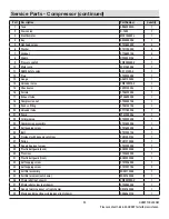
Page 25: ...ting ST081301AV 1 20 Unloader tube ST117802AV 1 21 Pump VT472200AJ 1 22 Oil drain plug ST022300AV 1 23 Compression assembly ST018300AV 1 24 Self tapping screw ST016500AV 4 25 Belt BT013001AV 1 26 Flyw...

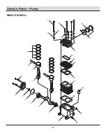
Page 26: ...26 Service Parts Pump MODEL VT472200AJ 18 17 15 14 12 13 19 20 21 22 24 23 25 26 27 28 1 2 3 2 4 5 6 7 8 9 10 11 16...

Page 27: ...rew 4 15 Flange head screw 2 16 Washer 2 17 Air filter assembly VH901700AV 1 18 Air filter element VH901800AV 1 19 Pump head 1 20 Valve plate gasket 1 21 O ring VT036700AV 1 22 Valve plate 1 23 Cylind...

Page 28: ...s problems missing parts Before returning to the store call Husky Customer Service 8 a m 6 p m EST Monday Friday 1 888 43 HUSKY HUSKYTOOLS COM Retain this manual for future use Document Number IN63960...

Reviews: