background image

13

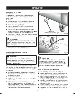
Fig. 5.2

COIL HOSE WITH QUICK 

COUPLER ATTACHED

PNEUMATIC 

TOOL 

(NOT INCLUDED)

MALE QUICK-

CONNECT PLUG

OPERATION

   WARNING:

Always wear safety goggles or safety glasses with 
side shields when operating power tools. Failure to do 
so could result in objects being thrown into your eyes 
resulting in possible serious injury.

   WARNING:

Do not allow familiarity with tools to make you careless. 
Remember that a careless fraction of a second is 
sufficient to inflict serious injury.

CAUTION:

Do not use in an environment that is dusty or otherwise 
contaminated. Using the air compressor in this type of 
environment may cause damage to the unit.

   WARNING:

Always ensure the switch is in the 

OFF (O)

 position and the 

regulator pressure gauge reads zero before changing air 
tools or disconnecting the hose from the air outlet. Failure 
to do so could result in possible serious personal injury.

Fig. 5.1

DRAIN 

VALVE

PRESSURE 

REGULATOR KNOB

ON/OFF 

SWITCH

APPLICATIONS

Air compressors are utilized in a variety of air system 
applications. Match hoses, connectors, air tools, and 
accessories to the capabilities of the air compressor.

You may use this tool for purposes listed below:

  Operating small air tools such as brad nailers and staplers.
  Inflating tires, air beds, sports equipment, etc.

USING THE AIR COMPRESSOR

See Figures 5.1 - 5.2.

  Ensure tank drain valve is closed (see Fig. 5.1).
  Ensure ON/OFF power switch is in the 

OFF


(O)

 position 

and air compressor is unplugged (see Fig. 5.1).

  Ensure Pressure Regulator Knob is turned fully 

counterclockwise (see Fig. 5.1).

  Connect air powered tools to air hose by inserting the 

male quick-connect plug to the quick-coupler at the end 
of the hose (see Fig. 5.2).

  Connect the power cord to the power supply.
  Turn the switch 

ON (I)

.

  Rotate pressure regulator knob to desired line 

pressure. Turning the knob clockwise increases 
air pressure at the outlet; turning counterclockwise 
reduces air pressure at the outlet.


NOTE:

 Before connecting or disconnecting air tools turn 

the regulator knob counter-clockwise to stop the flow of air.

  Following all safety precautions in this manual and the 

manufacturer’s instructions in the air tool manual, you 
may now proceed to use your air-powered tool.

  If using an inflation accessory with a quick-connect 

fitting, control the amount of air flow with the pressure 
regulator knob. Turning the knob fully counter-clockwise 
will completely stop the flow of air.


NOTE:

 Always use the minimum amount of pressure 

necessary for your application. Using a higher pressure 
than needed will drain air from the tank more rapidly 
and cause the unit to cycle on more frequently.

  When finished, always drain the tank and unplug the 

unit. Never leave the unit plugged in and/or running 
unattended.

   WARNING:

Check the air tool manual to insure the correct air pressure 
regulator setting for optimum operation of your air tools. If you 
are using an air tool not originally included with the air tool kit 
supplied with this air compressor, your tool may require more air 
consumption than this air compressor is designed to supply.
Always read your air tool owner’s manual to match the correct 
air supply to your air tool to avoid damage to the tool or risk of 
personal injury.

Summary of Contents for 2G110DPNG

Page 1: ...UFACTURED TO USKY S HIGH STANDARD FOR DEPENDABILITY EASE OF OPERA TION AND OPERATOR SAFETY 7HEN PROPERLY CARED FOR IT WILL GIVE YOU YEARS OF RUGGED TROUBLE FREE PERFORMANCE 7 2 4O REDUCE THE RISK OF I...

Page 2: ...this product making it easy to maintain and operate 2 6 8LMW GSQTVIWWSV TYQT MW RSX IUYMTTIH ERH WLSYPH RSX FI YWIH XS WYTTP FVIEXLMRK UYEPMX EMV HHMXMSREP IUYMT QIRX SYPH FI RIGIWWEV XS TVSTIVP JMPX...

Page 3: ...IGXMSR MPP FI VIUYMVIH MR WSQI IRZMVSRQIRXW SV I EQTPI XLI SVOMRK EVIE QE MRGPYHI I TSWYVI XS E RSMWI PIZIP LMGL GER PIEH XS LIEVMRK HEQEKI 8LI IQTPS IV ERH YWIV QYWX IRWYVI XLEX ER RIGIWWEV LIEVMRK T...

Page 4: ...QEMRXIRERGI TIVJSVQIH F YRUYEPMJMIH TIVWSRRIP QE VIWYPX MR E VMWO SJ MRNYV MWGSRRIGX TS IV WYTTP STIR HVEMR ZEPZI XS HI GSQTVIWW XERO ERH EPPS EXIV XS HVEMR ERH EPPS EMV GSQTVIWWSV XS FIGSQI GSSP XS...

Page 5: ...S 4AKE CARE NOT TO BLOW DUST AND DIRT TOWARDS YOURSELF OR OTHERS OLLOWING THIS RULE WILL REDUCE THE RISK OF SERIOUS INJURY 0ROTECT YOUR LUNGS 7EAR A FACE OR DUST MASK IF THE OPERATION IS DUSTY OLLOWIN...

Page 6: ...QEVOIH QE MQYQ TVIWWYVI SJ EXXEGLQIRX S RSX YWI EX TVIW WYVI KVIEXIV XLER 47 Risk to hearing Always wear ear protection when using this tool Failure to do so may result in hearing loss Risk of serious...

Page 7: ...I HEQEKI IJSVI FIKMRRMRK TS IV XSSP STIVEXMSR EP E W IEV WEJIX KSKKPIW WEJIX KPEWWIW MXL WMHI WLMIPHW SV E JYPP JEGI WLMIPH LIR RIIHIH I VIGSQQIRH MHI MWMSR 7EJIX 1EWO JSV YWI SZIV I IKPEWWIW SV WXERH...

Page 8: ...or and a grounding plug The plug must be plugged into a matching outlet that is properly installed and grounded in accordance with all local codes and ordinances Do not modify the plug provided If it...

Page 9: ...NT CONTAINED WITHIN A METAL OR PLASTIC HOUS ING ATTACHED TO THE COMPRESSOR CYLINDER HEAD WHICH REMOVES IMPURITY FROM THE INTAKE AIR OF THE COMPRESSOR IR 4ANK YLINDRICAL COMPONENT WHICH CONTAINS THE CO...

Page 10: ...ir Pressure 110 psi max Lubrication Oil Free Gauges 1 5 in diameter Input 120 V 60 Hz AC only 1 8 Amps Net Weight 19 6 lbs Fig 2 TIRE GAUGE TANK PRESSURE GAUGE AIR OUTLET FITTING THUMB LOCK CONNECTOR...

Page 11: ...T TO MODIFY THIS TOOL OR CREATE ACCESSO RIES NOT RECOMMENDED FOR USE WITH THIS TOOL NY SUCH ALTERATION OR MODIFICATION IS MISUSE AND COULD RESULT IN A HAZARDOUS CONDITION LEADING TO POSSIBLE SERIOUS P...

Page 12: ...ted REGULATOR PRESSURE GAUGE TANK PRESSURE GAUGE PRESSURE REGULATOR KNOB Fig 4 Fig 3 SAFETY VALVE ON OFF SWITCH OVERLOAD PROTECTOR This air compressor is equipped with a thermal overload device which...

Page 13: ...fully counterclockwise see Fig 5 1 Connect air powered tools to air hose by inserting the male quick connect plug to the quick coupler at the end of the hose see Fig 5 2 Connect the power cord to the...

Page 14: ...re stem Fig 8 Ensure the compressor is plugged in and switch to the ON position Open the ball valve at the base of the inflation hose to begin inflating Fig 9 You may adjust air flow by turning the ba...

Page 15: ...needle or nozzle into the connector and fold the lever over A until it is locked securely Fig 11 Ensure the compressor is plugged in and switch to the ON position Open the ball valve at the base of t...

Page 16: ...HE SAFETY VALVE TO RELEASE AIR FOR THREE TO FIVE SECONDS 2ELEASE THE RING IR MUST IMMEDIATELY STOP ESCAPING WHEN THE RING IS RELEASED NY CONTINUED LOSS OF AIR AFTER RELEASING THE SAFETY VALVE RING IND...

Page 17: ...T FROM POWER SUP PLY AND ALLOW UNIT TO COOL TO THE TOUCH BEFORE CLEANING OR MAKING REPAIRS ON THE AIR COMPRESSOR 2 4 UMIDITY IN THE AIR CAUSES CONDENSATE TO FORM IN THE AIR TANK 4HIS CONDENSATE SHOULD...

Page 18: ...compressor to service center Thermal overload protector cuts out repeatedly Low voltage Lack of proper ventilation room temperature too high Wrong gauge wire or length of extension cord Check with vo...

Page 19: ...not cover normal wear and tear or any malfunction failure or defect resulting from misuse abuse neglect alteration modification or repair by other than a service center authorized to repair HUSKY bran...

Page 20: ...OPERATOR S MANUAL 2G110DPNG 2 GALLON DUAL OUTPUT AIR COMPRESSOR CUSTOMER SERVICE 1 866 242 4298...

Page 21: ...AS ESTRICTAS NORMAS DE USKY PARA BRINDAR FIABILIDAD FACILIDAD DE USO Y SEGURIDAD PARA EL OPERADOR ON EL DEBIDO CUIDADO LE BRINDAR MUCHOS A OS DE S LIDO Y EFICIENTE FUNCIONAMIENTO 6 24 0ARA REDUCIR EL...

Page 22: ...a no est equipado y debe evitarse utilizarlo para suministrar aire para respirar Es necesario equipo adicional para filtrar y purificar debidamente el aire a fin de que cumpla las especificaciones m n...

Page 23: ...se de que se use protecci n ocular adecuada Recomendamos una careta protectora de visi n amplia encima de los anteojos normales o de los anteojos de seguridad que ofrecen protecci n frontal y lateral...

Page 24: ...umplimiento de las instrucciones de mantenimiento puede significar un riesgo de lesiones REGLAS DE SEGURIDAD ESPEC FICAS Familiar cese con su herramienta el ctrica Lea cuidadosamente el manual del ope...

Page 25: ...I N DEL CORD N EL CTRICO ON EL CUMPLIMIENTO DE ESTA REGLA SE REDUCE EL RIESGO DE UNA DESCARGA EL CTRICA O INCENDIO UNCA USE UN ADAPTADOR EL CTRICO CON ESTA CLAVIJA DE CONEXI N A TIERRA 2EVISE PARA VER...

Page 26: ...s protectores con protecci n lateral o una careta protectora completa Precauciones para su seguridad El rea de rociado debe estar bien ventilada No fume mientras est rociando con pistola ni roc e dond...

Page 27: ...de comenzar a utilizar una herramienta el ctrica p ngase siempre gafas de seguridad anteojos protectores con protecci n lateral o careta completa cuando sea necesario Recomendamos la careta protector...

Page 28: ...c c Una ca da considerable de voltaje causa una p rdida de potencia y el recalentamiento del motor Si el compresor no funciona al conectarlo en una toma de corriente vuelva a revisar el suministro de...

Page 29: ...mite predeterminado GLOSARIO DE T RMINOS Bomba Es el dispositivo que produce el aire comprimido mediante un pist n de vaiv n contenido dentro del cilindro Filtro de aire Es un elemento poroso contenid...

Page 30: ...8 A s lo corr alt Peso neto 8 9 kg 19 6 lb Fig 2 V LVULA DE DRENAJE PERILLA DE REGULACI N DE PRESI N PIE INTERRUPTOR DE ENCENDIDO APAGADO MAN METRO REGULADOR CALIBRE DE LAS RUEDAS MAN METRO DEL TANQU...

Page 31: ...los art culos enumerados en la lista de empaquetado Inspeccione cuidadosamente el compresor y las herramientas para asegurarse de que no haya sufrido ninguna rotura o da o durante el transporte No des...

Page 32: ...cial V LVULA DE DRENAJE MAN METRO REGULADOR MAN METRO DEL TANQUE PERILLA DE REGULACI N DE PRESI N Fig 3 V LVULA DE SEGURIDAD INTERRUPTOR DE ENCENDIDO APAGADO Fig 4 PROTECTOR CONTRA LA SOBRECARGA Este...

Page 33: ...al racor r pido que hay en el extremo de la manguera consulte la Fig 5 2 Conecte el cord n al suministro de corriente Ponga el interruptor en la posici n de encendido I Gire la perilla de regulaci n...

Page 34: ...presor est enchufado y ponerlo en posici n ON Abrir la v lvula esf rica de la base del tubo de inflado para empezar a inflar Fig 9 Puede ajustar la salida de aire girando la v lvula esf rica entre 0 9...

Page 35: ...apropiada o boquilla en el conector y doblar la palanca A hasta que se cierre firmemente Fig 11 Asegurarse de que el compresor est enchufado y la posici n en ON Abrir la v lvula esf rica de la base d...

Page 36: ...pague el compresor Tire del aro de la v lvula de seguridad para soltar aire durante tres o cinco segundos Suelte el aro Al soltar el aro el aire debe dejar de salir de inmediato Cualquier p rdida de a...

Page 37: ...ducir lesiones corporales serias Las herramientas el ctricas que se utilizan en materiales de fibra de vidrio paneles de yeso para paredes compuestos de resanar o yeso est n sujetas a desgaste acelera...

Page 38: ...ector contra sobrecarga t rmica interrumpe la corriente continuamente Voltaje baio Ventilaci n insuficiente temperatura ambiental demasiado elevada Cord n de extensi n de calibre o longitud equivocado...

Page 39: ...rant a no cubre el desgaste debido al uso normal ni ninguna anomal a fallo o defecto producido por el uso incorrecto el abuso la negligencia la alteraci n la modificaci n o la reparaci n por parte de...

Page 40: ...9039427 B MANUAL DEL USUARIO 2G110DPNG COMPRESOR DE AIRE DE 8 LITROS 2 GALONES DE SALIDA DOBLE SERVICIO DE CLIENTE 1 866 242 4298 Printed in China...

Reviews: