background image


9 HUSKYTOOLS.com


  Please contact 1-888-43-HUSKY for further assistance.

Part

Description

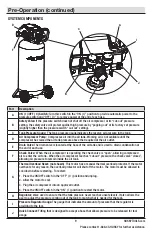
A

ON ( I )/OFF ( 0 ) Switch: 

Turn this switch in the “ON ( I )” position to provide automatic power to the 

pressure switch and “OFF ( O )” to remove power at the end of each use.

B

Safety Valve: 

If the pressure switch does not shut off the air compressor at its “cut-out” pressure 

setting, the safety valve will protect against high pressure by “popping out” at its factory set pressure 

(slightly higher than the pressure switch “cut-out” setting).

C

Tank Pressure Gauge: 

 The tank pressure gauge indicates the reserve air pressure in the tank. 

D

Air Compressor Pump: 

 Compresses air into the air tank. Working air is not available until the 

compressor has raised the air tank pressure above that required at the air outlet.

E

Drain Valve

: The drain valve is located at the base of the air tank and is used to drain condensation at 

the end of each use.

F

Check Valve: 

 When the air compressor is operating, the check valve is “open”, allowing compressed 

air to enter the air tank.  When the air compressor reaches “cut-out” pressure, the check valve “closes”, 

allowing air pressure to remain inside the air tank.

G

Thermal Overload Reset: (not shown)  

This motor has a manual thermal overload protector. If the motor 

overheats for any reason, the overload protector will shut off the motor.  The motor must be allowed to 

cool down before restarting.  To restart:
1.  Place the ON/OFF switch in the “OFF” ( O ) position and unplug.
2.  Allow the motor to cool.
3.  Plug the air compressor into an approved outlet.
4.  Place the ON/OFF switch in the “ON” ( I ) position to restart the motor.

H

Regulator: 

Valve used to ensure that the tank pressure never reaches unsafe levels. It also allows the 

user to adjust the pressure coming out of the tank to match what is needed for the task.

I

Pressure Regulator Gauge:

 The gauge that indicates the amount of pressure that the regulator is 

providing to the tool.

J

Quick Connect: 

Fitting that is designed to accept a hose that allows pressure to be released for tool 

usage.

SYSTEM COMPONENTS

Pre-Operation (continued)

C

B

I

H

J

A

D

F

E

Summary of Contents for C201H

Page 1: ...to enhance your home Visit us online to see our full line of products available for your home improvement needs Thank you for choosing Husky USE AND CARE GUIDE 20 GALLON PORTABLE AIR COMPRESSOR Quest...

Page 2: ...s gases or dust Power tools create sparks which may ignite the dust or fumes Keep bystanders children and visitors away while operating tools Distractions can cause you to lose control WARNING This co...

Page 3: ...ry or long hair can be caught in moving parts WARNING Never touch any exposed metal parts on compressor during or immediately after operation The compressor will remain hot for several minutes after o...

Page 4: ...er direct a jet of compressed air toward people or animals Protect your lungs Wear a face or dust mask if the operation is dusty Do not use this air compressor to spray chemicals Your lungs can be dam...

Page 5: ...et caught on lumber tools or other obstructions while you are working with a power tool Failure to do so can result in serious personal injury WARNING Check extension cords before each use If damaged...

Page 6: ...te grounding plug The plug must be plugged into an outlet that is properly installed and grounded in accordance with all local codes and ordinances WARNING Improper installation of the grounding plug...

Page 7: ...mum branch circuit requirement 15 A Fuse type Time delay Net weight 73 lbs DUTY CYCLE This air compressor pump is capable of running continuously However to prolong the life of your air compressor it...

Page 8: ...sor is operating the check valve is open allowing compressed air to enter the air tank When the air compressor reaches cut out pressure the check valve closes allowing air pressure to remain inside th...

Page 9: ...ronment may cause damage to the unit NOTICE Long lengths of electrical wiring could cause power loss to the motor Place the air compressor in a clean dry and well ventilated area The air compressor mu...

Page 10: ...or safety glasses with side shields when operating power tools Failure to do so could result in objects being thrown into your eyes resulting in possible serious injury The compressor is assembled at...

Page 11: ...ure rating CAUTION Risk of unsafe operation Compressed air from the unit may contain wa ter condensation and oil mist Do not spray un fil tered air at an item that could be damaged by moisture Some ai...

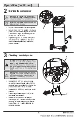
Page 12: ...ould fly up and hit you Failure to heed this warning could result in death or serious personal injury The safety valve automatically releases air when the receiver pressure exceeds the preset maximum...

Page 13: ...of air flow with the pressure regulator knob Using a higher pressure than needed will drain air from the tank more rapidly and cause the unit to cycle on more frequently Rotate the pressure regulator...

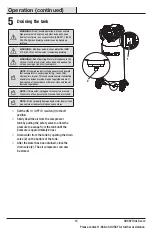
Page 14: ...drain point e g tanks filter after coolers dryers This condensate contains lubricating oil and or substances which may be regulated and must be disposed of in accordance with local state and federal l...

Page 15: ...rts Use of any other parts may create a hazard or cause product damage WARNING Always release all pressure disconnect from power supply and allow unit to cool to the touch before cleaning or making re...

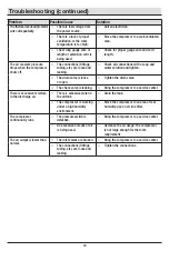
Page 16: ...Release the air from the tank until the compressor restarts automatically The motor hums while running slowly or it doesn t run at all There is low voltage from the power source Call an electrician Th...

Page 17: ...e or open Tighten the drain valve The check valve is leaking Bring the compressor to a service center There is excessive moisture in the discharge air There is excessive water in the air tank Drain th...

Page 18: ...19 HUSKYTOOLS com Please contact 1 888 43 HUSKY for further assistance Service Parts C201H AIR COMPRESSOR...

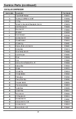
Page 19: ...Valve E109170 12 Hose Clamp Set of 2 E106648 13 Switch Rocker E106633 14 Hose E106636 15 Cup E106625 16 Screw 10 14 Plastite T20 x 75 E106646 17 Safety Valve E108520 18 Gauge E108512 19 Shroud Top E10...

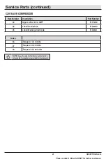
Page 20: ...part number field without a number listed is not available Descriptions are provided for reference only Item Number Description Part Number 33 Nipple 250 18 X 2 0NPT E107858 34 Label Hot Surface E106...

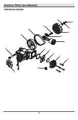
Page 21: ...22 Service Parts continued PUMP MOTOR ASSEMBLY...

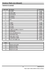
Page 22: ...9 Fan Motor E108869 10 Fan Pump E108870 11 Fan Mount E108871 12 Headbolt 250 20UNC x 1 75 Set of 4 E108872 13 Head Grommet E108873 14 Screw 375 24UNF 2A x 1 25 E108874 15 Screw 250 20 x 500 E109129 1...

Page 23: ...problems missing parts Before returning to the store call Husky Customer Service 8 a m 6 p m EST Monday Friday 1 888 43 HUSKY HUSKYTOOLS COM Retain this manual for future use Document Number E108331 0...

Reviews: