background image

6

ASSEMBLY / PRE-OPERATION

Read these instructions and this manual in its entirety before you attempt to assemble or operate your new 

snow thrower.  Reading the entire manual will familiarize you with the unit, which will assist you in assembly, 

operation and maintenance of the product.

Your new snow thrower has been as sem bled at the factory with the ex cep tion of those parts left unassembled for shipping 

purposes. All parts such as nuts, washers, bolts, etc., necessary to com plete the as sem bly have been placed in the parts 

bag. To ensure safe and proper operation of your snow thrower, all parts and hard ware you assemble must be tightened 

se cure ly. Use the correct tools as nec es sary to ensure proper tightness.

REMOVE SNOW THROWER FROM CAR TON

1.  Remove all accessible loose parts and parts boxes 

from carton.

2.  Cut down all four corners of carton and lay panels flat.
3.  Remove the two (2) screws securing the auger housing 

to the pallet.

4.  Remove all packing materials ex cept plastic tie holding 

speed control rod to lower handle.

5.  Remove the two (2) plastic ties securing the upper 

handle to the pallet.

6.  Remove snow thrower from carton and check carton 

thor ough ly for ad di tion al loose parts. 

HOW TO SET UP YOUR SNOW THROWER 

TOOL BOX (See Fig. 10)

A toolbox is provided on your snow thrower. The toolbox is 

located on top of the belt cover.  Store the extra shear bolts, 

nuts and multi-wrench provided in parts bag in the toolbox.

NOTE:

 The multi-wrench may be used for assembly of the 

chute rotator head to snow thrower and making ad just ments 

to the skid plates.

UNFOLD UPPER HANDLE

1.  Raise upper handle to the operating position and 

tight en handle knobs securely.  Additional carriage 

bolts, washers and handle knobs are in bag of parts.  

Use to secure upper handle to lower handle.  Install 

in lower holes in handles.

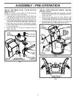
INSTALL SPEED CONTROL ROD (See Figs. 1 and 2)

1.  Remove plastic tie securing rod to lower handle.
2.  Insert rod into speed control bracket and secure with 

retainer spring.

SPEED

CONTROL 

ROD

HANDLE 

KNOB

LOWER 

HANDLE

PLASTIC TIE

UPPER 

HANDLE

FIG. 1

SPEED CON TROL ROD

SPEED 

CONTROL 

BRACKET

SPEED 

CONTROL 

LEVER

FIG. 2

RETAINER 

SPRING

Summary of Contents for 1827EXLT

Page 1: ...ontaining up to 10 ethanol E10 is acceptable for use in this machine The use of any gasoline exceeding 10 ethanol E10 will void the product warranty Please read the owner s manual carefully and make sure you understand the instructions before using the machine ...

Page 2: ...e machine Operation 1 Do not put hands or feet near or under rotating parts Keep clear of the discharge opening at all times 2 Exercise extreme caution when operating on or cross ing gravel drives walks or roads Stay alert for hidden hazards or traffic 3 After striking a foreign object stop the engine motor remove the wire from the spark plug disconnect the cord on electric motors thoroughly inspe...

Page 3: ...ity or light Always be sure of your footing and keep a firm hold on the handles Walk never run 16 Never touch a hot engine or muffler 17 When using your snowthrower in for long periods of time in deep snow be aware of snow and ice build up between the track components This may cause a loss of performance in the drive system Clean out snow and debris between tracks in regular intervals Clearing a C...

Page 4: ...AROFTHESNOW THROWER HOUSING YOUSHOULDRECORDBOTHSERIALNUMBERAND DATE OF PURCHASE AND KEEP IN A SAFE PLACE FOR FUTURE REFERENCE CUSTOMER RESPONSIBILITIES Read and observe the safety rules Follow a regular schedule in maintaining caring for and using your snow thrower Follow the instructions under Maintenance and Stor age sections of this owner s manual MAINTENANCE 16 17 SERVICE AND ADJUSTMENTS 18 20...

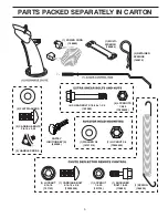
Page 5: ...ITION KEY S 443059 1 MULTI WRENCH 180684 1 LOCKNUT 5 16 18 751153 1 CARRIAGE BOLT 5 16 18 x 5 8 72250505 1 LOCKNUT 1 4 20 191730 1 SHOULDER BOLT 1 4 20 179829 1 SPRING 184505 1 POWER CORD 198563 6 SHEAR BOLTS 1 4 20 x 1 3 4 192090 6 LOCKNUTS 1 4 20 73800400 2 FLAT WASHERS 2 CARRIAGE BOLTS 3 8 16 x 2 25 2 HANDLE KNOBS ...

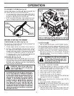
Page 6: ...ls except plastic tie holding speed control rod to lower handle 5 Remove the two 2 plastic ties securing the upper handle to the pallet 6 Remove snow thrower from carton and check carton thoroughly for additional loose parts HOW TO SET UP YOUR SNOW THROWER TOOL BOX See Fig 10 A toolbox is provided on your snow thrower The toolbox is located on top of the belt cover Store the extra shear bolts nuts...

Page 7: ...yl sleeve and spring from bag of parts and retrieve the auger control rod from carton chute tray Slide straight rod end through the small hole in the vinyl sleeve Hook spring in hole in rod end 2 Hook end of spring into control arm with loop opening up as shown See Fig 5 3 Withtopendofrodpositionedunderrightsideofcontrol panel push down on rod and insert end of rod into hole in auger control brack...

Page 8: ...hten securely CHUTE ROTATOR HEAD 3 8 WASHER 3 8 LOCKNUT THREADED STUD PIN ROTATOR HEAD MOUNTING BRACKET CHUTE BRACKET FIG 7 ALIGN BEFORE TIGHTENING LOCKNUT INSTALL CHUTE DEFLECTOR REMOTE CONTROL See Figs 8 and 9 1 Install remote cable bracket to discharge chute with 5 16 18 carriage bolt and 5 16 18 locknut as shown Tighten securely 2 Install remote cable eyelet to chute deflector with 1 4 20shoul...

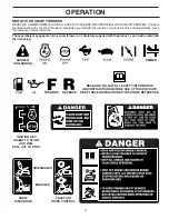
Page 9: ...s Save this manual for future reference These symbols may appear on your snow thrower or in literature supplied with the product Learn and understand their meaning FORWARD PRIMER IGNITION KEY INSERT TO START AND RUN PULL OUT TO STOP READ AND FOLLOW ALL SAFETY INFORMATION AND INSTRUCTIONS BEFORE USE OF THIS PRODUCT KEEP THESE INSTRUCTIONS FOR FUTURE REFERENCE DANGER OR WARNING REVERSE SNOW DISCHARG...

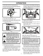
Page 10: ...cut through deep snowdrifts Toolbox used to store spare shear bolts locknuts and wrench Freewheel control disengages transmission for pushing the snowthrower with the engine off Safety ignition key must be inserted for the engine to start and run Remove when snow thrower is not in use Electric start button used for starting the engine Recoil auxiliary starterhandle usedforstartingengine Primer pum...

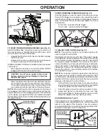
Page 11: ...heel control into FREEWHEELposition SeeFig 11 andheightadjustment locator into TRANSPORT MODE position See Fig 12 Pull freewheel control out to FREEWHEEL position Set height adjustment into TRANSPORT MODE To reengage transmission push control back in FREEWHEEL POSITION FIG 11 TRANSMISSION ENGAGED SET HEIGHT ADJUSTMENT See Figs 12 13 Your snow thrower is equipped with a foot controlled height adjus...

Page 12: ...trol lever to stop throwing snow USING THE CLEAN OUT TOOL See Fig 18 In certain snow conditions the discharge chute may be come clogged with ice and snow Use the clean out tool to dislodge this blockage When cleaning repairing or inspecting make certain all controls are disengaged and the au ger impellerandallmovingpartshavestopped Disconnect the spark plug wire and keep the wire away from the spa...

Page 13: ...harge chute direction without interrupting the snow throwing process DRIVE SPEED CONTROL LEVER TRACTION DRIVE CONTROL LEVER FIG 19 TO ADJUST SKID PLATES See Fig 21 NOTE The wrench provided in your parts bag may be used to adjust the skid plates Skid plates are located on each side of the auger housing and adjust the clearance between the scraper bar and the ground surface Adjust skid plates evenly...

Page 14: ... start the engine and let it run until the fuel lines and carburetor are empty Use fresh fuel next season SeeStorageInstructionsforadditional information Never use engine or carburetor cleaner products in the fuel tank or permanent damage may occur FIG 23 PRIMER SAFETY IGNITION KEY ON OFF SWITCH CHOKE CON TROL STARTER BUTTON FUEL SHUT OFF VALVE NOTE ALL ITEMS ARE SHOWN IN THEIR TYPICAL LOCATION AC...

Page 15: ... ing temperature WARM START ELECTRIC STARTER Follow the steps above keeping the choke control in the OFF position COLD START RECOIL STARTER 1 Insert safety ignition key tied to recoil start cord into ignition slot until it clicks DO NOT turn the key Keep the extra safety ignition key in a safe place 2 Place ON OFF switch in ON position 3 Rotate choke control to FULL position 4 Push the primer four...

Page 16: ...ked at least once each season Once a year you should replace the spark plug and check belts for wear A new spark plug will help your engine run better and last longer Follow the maintenance schedule in this manual NOTE Use only Original Equipment Manufacturer OEM parts to service this unit Failure to do so can cause the unit to malfunction and pose a risk of injury to the operator BEFORE EACH USE ...

Page 17: ...in any oil trapped inside the engine See TO REMOVE TRACKS in the Service and Adjustments section of this manual 1 Remove safety ignition key and disconnect spark plug wire from spark plug Place wire where it cannot come in contact with spark plug 2 Clean area around drain plug 3 Remove drain plug and drain oil in a suitable container 4 Install drain plug and tighten securely 5 Wipe off any spilled...

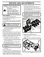
Page 18: ... capscrew shear bolts and hex nuts Should a foreign object or ice become lodged in the impeller the capscrews are designed to break preventing damage to any other com ponents If impeller does not turn when auger control lever is engaged check to see if the capscrews have sheared AUGER SHAFT 1 4 20 x 2 SHOULDER SHEAR BOLT 1 4 20 LOCKNUT IMPELLER SHAFT 1 4 20 x 1 5 8 CAPSCREW SHEAR BOLT 1 4 20 LOCKN...

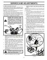
Page 19: ...elt s be replaced by a service center department NOTE It is recommended that both the auger and traction drive belt be replaced at the same time The V belts on your snow thrower are of special construc tion and should be replaced by original equipment manu facturer OEM belts available from your nearest service center department Using other than OEM belts can cause personal injury or damage to the ...

Page 20: ...O ADJUST CABLE TENSION See Fig 28 Adjust cable tension by turning the adjuster turn buckle located on the right hand cable Grasp the long section tightly and turn the short section to lengthen the adjuster Adjust until cable is snug ADJUSTER TURN BUCKLE FIG 28 ENGINE SPEED Never tamper with the engine governor which is factory set for proper engine speed Overspeeding the engine above the factory h...

Page 21: ... system of an engine while in storage Empty the fuel tank by starting the engine and letting it run until the fuel lines and carburetor are empty Never use engine or carburetor cleaner products in the fuel tank or permanent damage may occur Use fresh fuel next season NOTE Fuel stabilizer is an acceptable alternative in min imizing the formation of fuel gum deposits during storage Add stabilizer to...

Page 22: ... or clogged muffler 4 Clean or replace muffler Engine idles or runs roughly 1 Choke is in FULL position 1 Move choke to OFF position 2 Blockage in fuel line 2 Clean fuel line 3 Stale fuel 3 Empty fuel tank carburetor refill with fresh clean gasoline 4 Water in fuel 4 Empty fuel tank carburetor refill with fresh clean gasoline 5 Carburetor is in need of adjustment or overhaul 5 Contact an authorize...

Page 23: ...UDQW Q PRVW FDVHV WKHVH LWHPV DUH 127 PDQXIDFWXUHG E XVTYDUQD LQ ZKLFK FDVH WKH PD EH FRYHUHG VHSDUDWHO E WKHLU UHVSHFWLYH PDQXIDFWXUHU V ZDUUDQWLHV LI RQH LV SURYLGHG DQG LQFOXGHG ZLWK WKH SURGXFW DW WKH WLPH RI SXUFKDVH 7KH IROORZLQJ WUDQVPLVVLRQ WUDQVD OH PDQXIDFWXUHUV DQD GUR HDU 7XII 7RUT SURYLGH D ZDUUDQW IRU WKH WUDQVPLVVLRQ WUDQVD OH WR WKH XOWLPDWH SXUFKDVHU RU WR XVTYDUQD XVTYDUQD ZLOO D...

Page 24: ...RU PRGLILHG FXWWLQJ VKLHOGV JXDUGV RU VDIHW GHYLFHV P Q UHPRYHG GDPDJHG DLU ILOWHU H FHVVLYH GLUW DEUDVLYHV VDOW ZDWHU PRLVWXUH FRUURVLRQ UXVW YDUQLVK VWDOH IXHO RU DQ DGYHUVH UHDFWLRQ GXH WR LQFRUUHFW VWRUDJH SURFHGXUHV Q DLOXUHV GXH WR LPSURSHU VHW XS SUH GHOLYHU VHUYLFH RU UHSDLU VHUYLFH E DQ RQH RWKHU WKDQ DQ DXWKRUL HG XVTYDUQD VHUYLFLQJ GHDOHU GXULQJ WKH ZDUUDQW SHULRG R LUW FRQWDPLQDWHG JUH...

Page 25: ...Q SHQGDEOH RPSRQHQWV HDUV 12 55 17 12 55 17 6QRZ 7KURZHUV QJLQH 5HVLGHQWLDO HUR 7XUQ 0RZHUV 0 3URGXFW RPSRQHQW 5HVLGHQWLDO HUR 7XUQ 0RZHUV 5 2QO QJLQH 2WKHU 1RQ SHQGDEOH RPSRQHQWV HDUV GD V GD V 7LOOHUV QJLQH DWWHU HDU 3UR UDWHG 12 55 17 12 55 17 2WKHU 1RQ SHQGDEOH RPSRQHQWV HDUV 12 55 17 12 55 17 7LOOHU 7LQHV 12 55 17 12 55 17 RYHULQJ 7ULPPHUV QJLQH 2WKHU 1RQ SHQGDEOH RPSRQHQWV HDUV HDU GD V RQVX...

Page 26: ... G OO RWKHU 3UHVVXUH DVKHUV 3 3 3 3DUWV FFHVVRULHV LI SXUFKDVHG FFHVVRULHV H J JUDVV FDWFKHU EXPSHU JXDUG DFFHVVRULHV HWF HDU 12 55 17 12 55 17 3DUWV H J EHOWV EODGHV HWF GD V 12 55 17 12 55 17 3DUWV FFHVVRULHV LI UHSODFHG LQ DUUDQW 6HUYLFH 5HSODFHPHQW SDUWV DQG RU DFFHVVRULHV SURYLGHG XQGHU WKLV LPLWHG DUUDQW DUH ZDUUDQWHG RQO IRU WKH 1 RI WKH ZDUUDQW SHULRG DSSOLFDEOH WR WKH SDUW RU DFFHVVRU WKD...

Page 27: ...27 SERVICE NOTES ...

Page 28: ...08 01 2011 SR ...

Reviews: