3
22
540 06 82-01
531 03 06-23
502 50 19-01
Fuel system
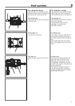
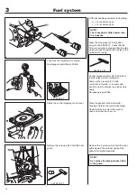
NOTE!
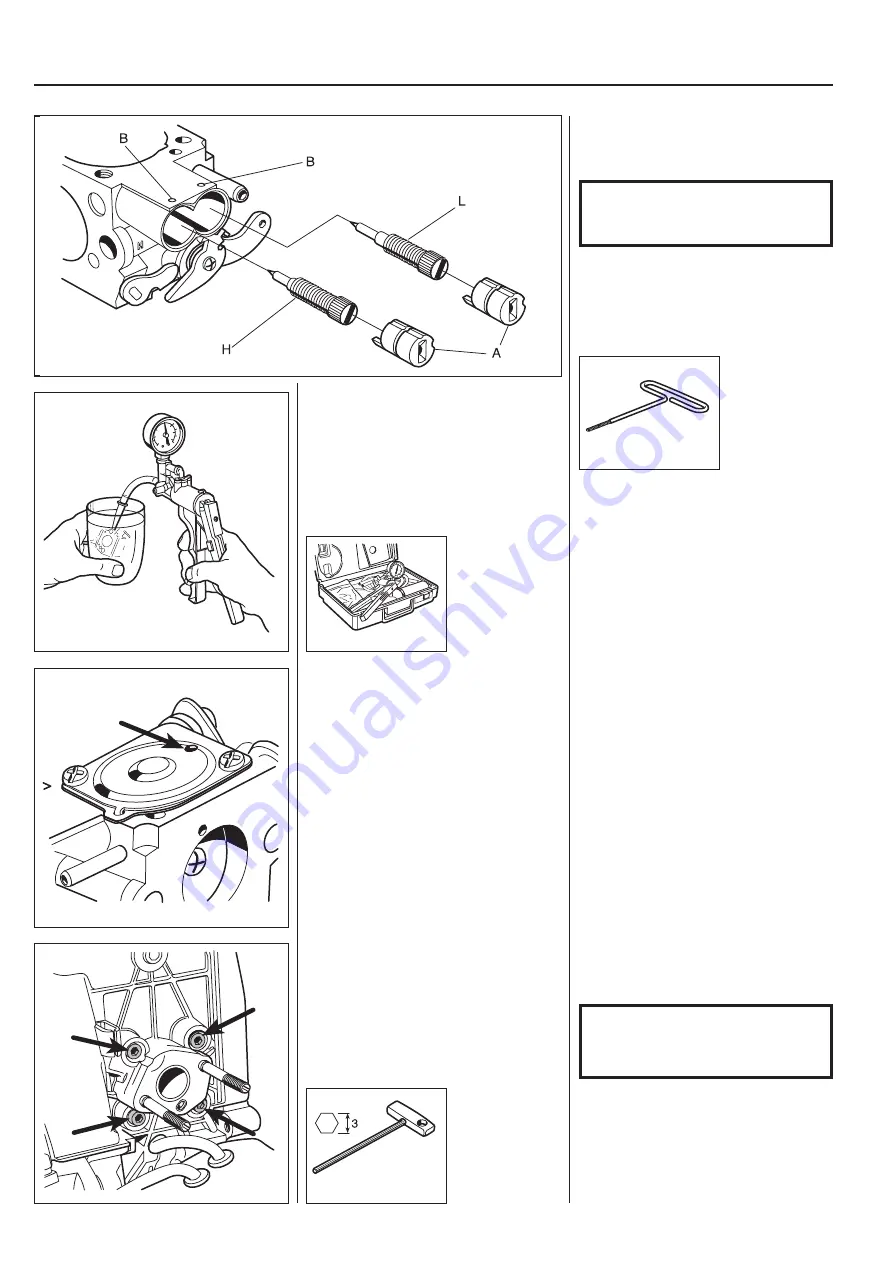
The H-needle is a little shorter than
the L-needle.
Fit the jet needles and adjust their setting.
H
=
1.2
revolution
open
L
=
1.2
revolution
open
Press the stop plugs (A) into position
using tool 540 06 82-01. Check that the
O-ring is correctly seated and that the stop
plug’s grooves
fi
t against the ball (B) in the
carburettor housing.
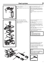
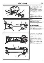
Remove the screws which hold the heat
guard
Remove the 4 screws which hold the heat
guard against the cylinder and pull the
guard off straight backwards.
NOTE!
Do not lose the brass sleeves fi tted
in the guard.
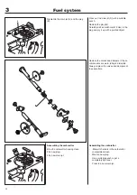
Check that the carburettor is sealed.
No leakage is permitted at 50 kPa.
Connect pressure tester 531 03 06-23 to
the fuel intake on the carburettor.
Pump up the pressure to 50 kPa.
Lower the carburettor in a vessel with
petrol in order to discover any leaks more
easily.
No leakage is permitted.
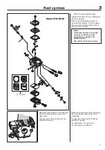
Attach the control diaphragm and cover.
Place the gasket on the carburettor
housing and then the control diaphragm.
Check that the air hole in the cover is
open and screw the cover on.
Summary of Contents for 241R
Page 1: ...Workshop manual 241R 241RJ English ...
Page 35: ...4 34 Centrifugal clutch ...
Page 49: ...6 48 Cylinder and piston ...
Page 59: ...58 8 List of tools ...
Page 62: ...2008W37 115 11 96 26 ...

