3
24
Fuel system
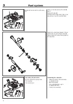
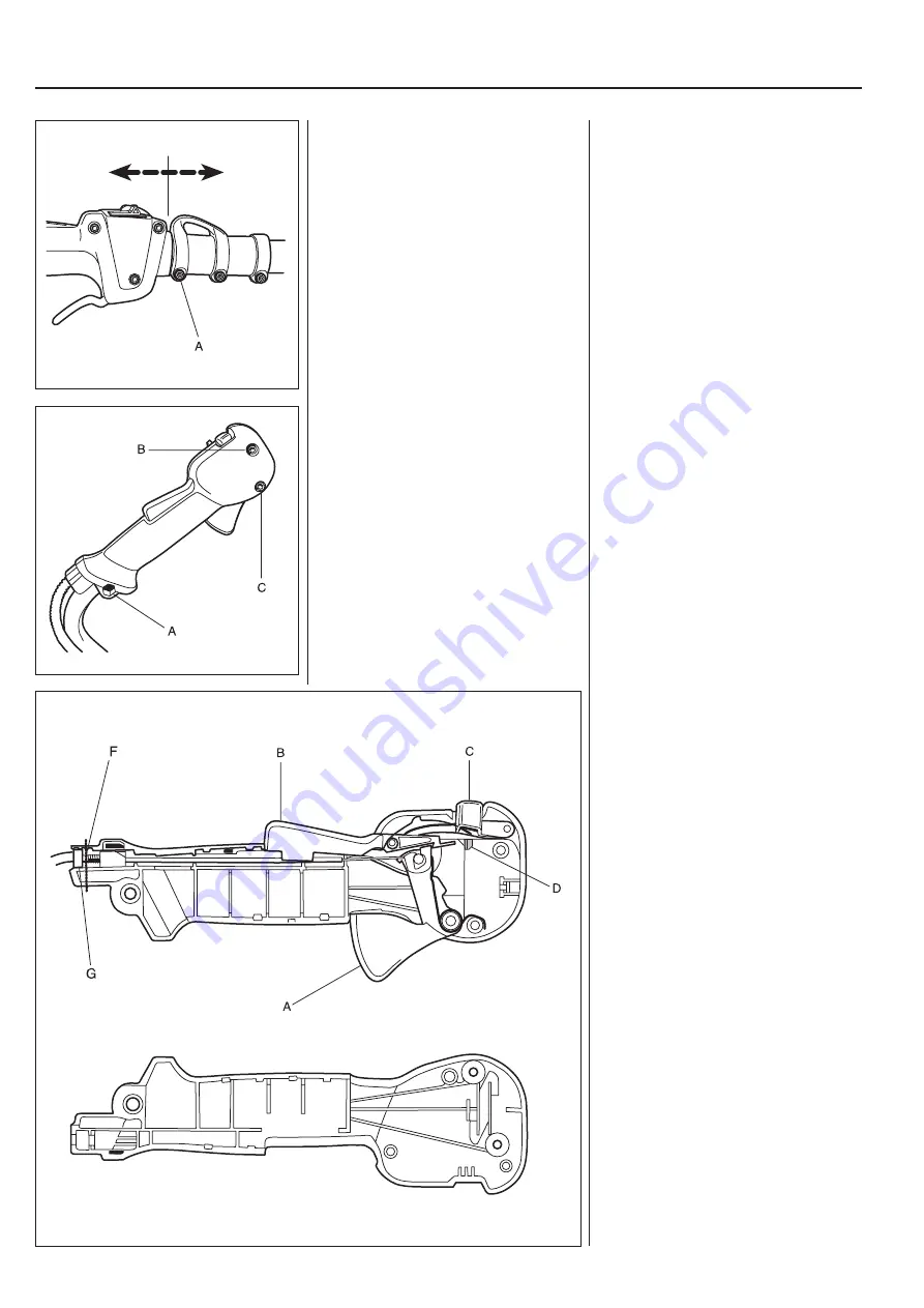
Dismantle the throttle control (A), the lock
against accidental acceleration (B) and
the start gas lock (C) for inspection and
possible replacement.
Now the stop switch can also be disman-
tled for possible replacement. Use a screw
driver and press the stop switch’s locking
wings (D).
G = Adjuster screw for start throttle speed.
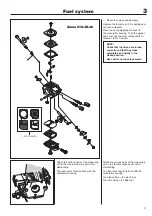
Tip!
Reassembly of the throttle easier if a thin
steel wire is wrapped around the handle
and bolt (F) in order to hold the throttle
cable and short-circuit cables in place.
Split the shaft.
Separate both halves of the throttle.
Slide the front vibration damper (7) off of
the shaft.
Assemble in the reverse order as set out
for dismantling.
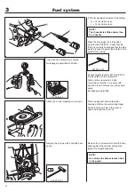
Loosen the screw (A) and pull away the
front part of the two-piece shaft.
Separate the throttle halves as described
above.
The front, ring shaped vibration damper (7
in the illustration above) can now be slid
off of the shaft for replacement.
Assemble the throttle in the reverse order
as set out for dismantling.
Make sure that:
• The throttle return spring is turned the
right way.
• The washer under the lock for unin-
tentional throttle activation is seated
correctly.
• Both rear rubber elements are in posi-
tion.
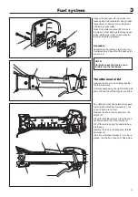
Throttle model R
Remove the bolt (A) and remove the
throttle from the handle.
Remove bolts (B) and (C).
Separate the halves of the throttle.
Throttle model R
Remove the bolt (A) that attaches the
throttle to the handle.
Be careful not to lose the nut.
Remove the throttle and remove bolts (B)
and (C).
Carefully separate the two halves of the
throttle.
Summary of Contents for 241R
Page 1: ...Workshop manual 241R 241RJ English ...
Page 35: ...4 34 Centrifugal clutch ...
Page 49: ...6 48 Cylinder and piston ...
Page 59: ...58 8 List of tools ...
Page 62: ...2008W37 115 11 96 26 ...

