4
33
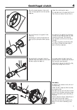
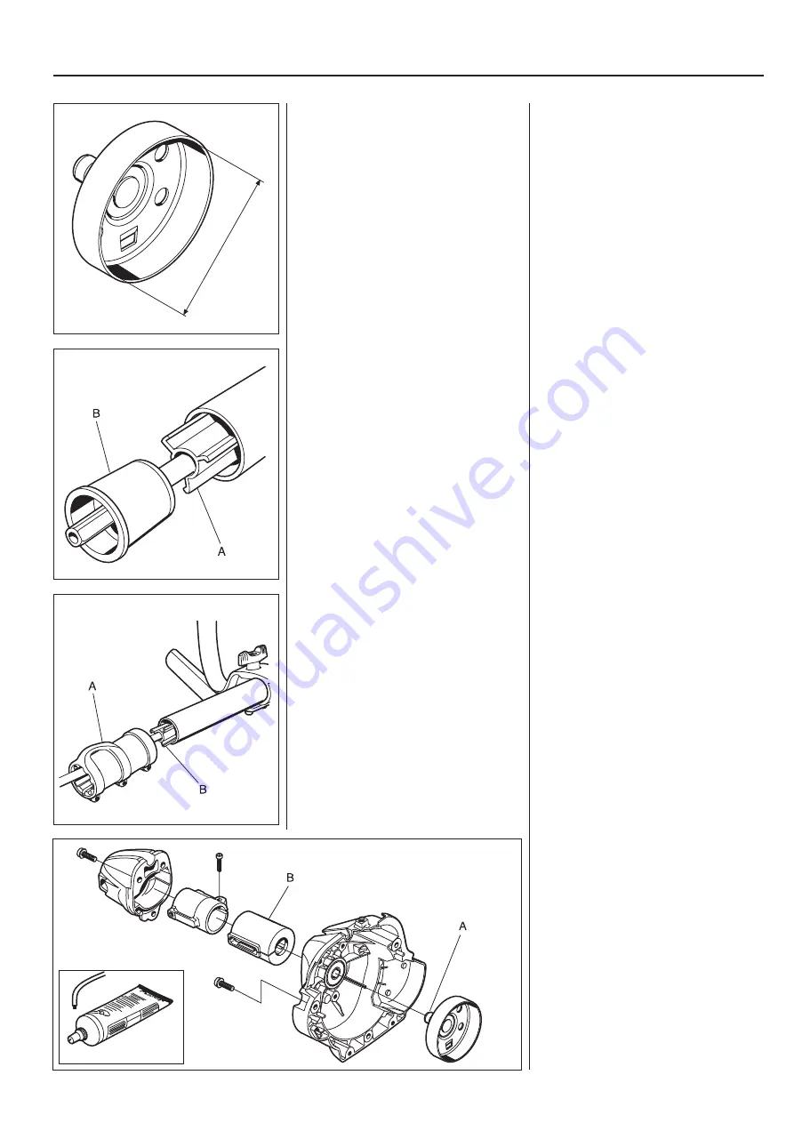
max. Ø 64.0 mm
503 80 17-01
Centrifugal clutch
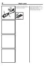
The shaft contains a long guide for the
drive axle.
Dismantling for possible replacement is
done by
fi
rst removing the plastic sleeve
(B).
The drive axle is guided in the shaft with
the help of a star shaped guide (A) which
the axle runs through. This prevents
axle oscillation, which in turn can cause
vibration.
The axle and guide can easily be pulled
out of the shaft once the sleeve (B) is
pried off with a screwdriver.
On models with a two-piece shaft, the
guide becomes accessible once the shaft
has been split (see chapter 3).
On models with a two-piece shaft, the
guide becomes accessible once the shaft
has been split (see chapter 3).
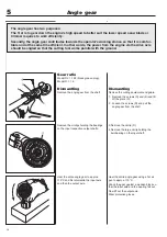
Dismantle the sleeve (A) and pull out the
guide (B) by pulling the drive axle.
Assembly
Assemble in the reverse order as set out
for dismantling.
Check that the circlips are
fi
tted correctly
in respective slots.
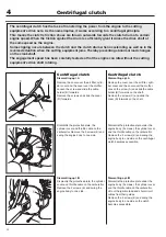
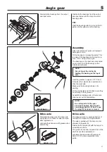
Lubricate the hole (A) in the clutch drum’s
connection on the drive axle using copper
paste to aid assembly and dismantling in
the future.
Rub the vibration element (B) with talc so
that it slides into position easier.
Lubricate the drive axle with grease no.
503 80 17-01 when assembling in the
guide.
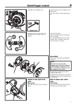
Check the inside diameter of the clutch
drum. If it exceeds 64.0 mm it should be
replaced.
Check the clutch drum for wear.
The diameter must not exceed 64.0 mm. If
this is the case replace the clutch drum.
Summary of Contents for 241R
Page 1: ...Workshop manual 241R 241RJ English ...
Page 35: ...4 34 Centrifugal clutch ...
Page 49: ...6 48 Cylinder and piston ...
Page 59: ...58 8 List of tools ...
Page 62: ...2008W37 115 11 96 26 ...

