background image

40

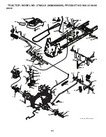
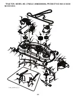
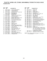
TRACTOR - MODEL NO. 2754GLS (96043006600), PRODUCT NO. 960 43 00-66

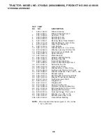
SEAT ASSEMBLY   


532 40 66-21 

Seat

532 18 01-66 

Bracket Pivot Fender

532 14 06-75 

Strap, Asm Fender

873 80 06-00 

Nut, Lock w/Ins. 3/8-16 unc

532 12 41-81 

Spring, Seat Cprsn

532 17 18-77 

Bolt 5/16-18 unc x 3/4 w/Sems

10  532 19 69-77 

Pan, Seat

21  532 17 18-52 

Bolt, Shoulder 5/16-18

37  873 80 05-00 

Nut, Lock 5/16-18 unc

40  532 19 76-61 

Handle Slide Seat

41  532 19 82-00 

Spring Latch Seat

43  874 76 06-12 

Bolt Fin Hex 3/8-16 unc x 3/4

44  819 13 38-12 

Washer 13/32 x 2-3/8 x 12 Ga.

KEY PART

NO. NO. 

DESCRIPTION

KEY PART

NO. NO. 

DESCRIPTION

NOTE:

  All component dimensions given in U.S. inches

         1 inch = 25.4 mm

2

6

1

40

10

37

37

21

21

3

41

7

8

7

8

8

8

seat-tex_6.5SL_2

44

43

6

Summary of Contents for 2754GLS

Page 1: ...03002 2754GLS Owner s Manual 96043006600 2008 12 ...

Page 2: ...ng brake stop engine and remove keys before dismounting Disengage blades when not mowing Shut off engine and wait for all parts to come to a complete stop before cleaning the machine removing the grass catcher or unclogging the discharge guard Operate machine only in daylight or good artificial light Do not operate the machine while under the influence of alcohol or drugs Watch for traffic when op...

Page 3: ...ch towed equipment except at the hitch point Follow the manufacturer s recommendation for weight limits for towed equipment and towing on slopes Never allow children or others in or on towed equip ment On slopes the weight of the towed equipment may cause loss of traction and loss of control Travel slowly and allow extra distance to stop V SERVICE SAFE HANDLING OF GASOLINE To avoid personal injury...

Page 4: ...the proper tools to service or repair this tractor Please read and retain this manual The instructions will enable you to assemble and maintain your tractor properly Always observe the SAFETY RULES CUSTOMER RESPONSIBILITIES Read and observe the safety rules Follow a regular schedule in maintaining caring for and using your tractor Follow the instructions under Maintenance and Stor age sections of ...

Page 5: ... Wheel 5 Large Retainer Springs 7 16 2 Smaller Retainer Springs 5 16 1 Locknut 3 8 16 1 Oil Drain Tube For Future Use 1 Shoulder Bolt Mower Front Wheel 1 Anti Sway Bar 1 3 4 O D Washers 1 1 1 4 O D Washer 5 1 3 16 O D Washers 2 Rear Lift Link Assemblies ...

Page 6: ... and function of controls Be sure all the above assembly steps have been com pleted Check engine oil level and fill fuel tank with gasoline Place freewheel control in transmission engaged position see TO TRANSPORT in Operation section of this manual Sit on seat in operating position depress brake pedal and set the parking brake Raise attachment lift lever to its highest position Remove key from ba...

Page 7: ...ward and check belt for proper routing in all mower pulley grooves Pivot bar towards you and insert other end of bar into hole in rear mower bracket D Move mower as needed to insert bar Secure with washer and retainer spring as shown using small 5 16 retainer spring NOTE Be sure mower side suspension arms A are point ing forward before sliding mower under tractor Slide mower under tractor until it...

Page 8: ...r spring Repeat on opposite side of tractor Turn steering wheel to position wheels straight for ward ATTACH FRONT LINK E Work from left side of tractor Insert rod end of link assembly through front hole in tractor front suspension bracket F and secure with7 16 retainer spring G through hole in link located behind the bracket Insert other end of link E into hole in front mower bracket H and secure ...

Page 9: ...perly leveled side to side front to rear for best cutting results Tires must be properly inflated for leveling Check mower and drive belts Be sure they are routed properly around pulleys and inside all belt keepers Check wiring See that all connections are still secure and wires are properly clamped Before driving tractor be sure freewheel control is in transmission engaged position see TO TRANS P...

Page 10: ...dentify safety inform ation about hazards which can result in death serious injury and or property damage DANGER indicates a hazard which if not avoided will result in death or serious injury WARNING indicates a hazard which if not avoided could result in death or serious injury CAUTION indicates a hazard which if not avoided might result in minor or moderate injury CAUTION when used without the a...

Page 11: ...H SWITCH Used to engage the mower blades or other attachments mounted to your tractor F IGNITION SWITCH Used for starting and stopping the engine G REVERSE OPERATION SYSTEM ROS ON POSITION Allows operation of mower or other powered attachment while in reverse H LIGHT SWITCH Turns the headlights on and off J CRUISE CONTROL LEVER Used to set forward movement of tractor at desired speed without holdi...

Page 12: ... and full speed fast position NOTE Failure to move throttle control between half and full speed fast position before stopping may cause engine to backfire Turnignitionkey F to STOP positionandremovekey Always remove key when leaving tractor to prevent unauthorized use Never use the choke to stop the engine IMPORTANT Leaving the ignition switch in any position other than STOP will cause the battery...

Page 13: ...tion Gauge wheels then keep the deck in proper position to help prevent scalping in most terrain conditions NOTE Adjust gauge wheels with tractor on a flat level surface Adjust mower to desired cutting height See TO AD JUST MOWER CUTTING HEIGHT in this section of manual With mower in desired height of cut position gauge wheels should be assembled so they are slightly off the ground Install gauge w...

Page 14: ...s absolutely necessary USING THE REVERSE OPERATION SYSTEM Only use if you are certain no children or other bystanders will enter the mowing area Depress brake pedal all the way down Withenginerunning turnignitionkeycounterclockwise to ROS ON position Look down and behind before and while backing Slowly depress reverse drive pedal to start move ment When use of the ROS is no longer needed turn the ...

Page 15: ... start pull the choke control out and retry WARM WEATHER STARTING 50 F and above When engine starts slowly push choke control in until the engine begins to run smoothly If the engine starts to run roughly pull the choke control out slightly for a few seconds and then continue to push the control in slowly The attachments and ground drive can now be used If the engine does not accept the load resta...

Page 16: ...heel lever while the engine is running To ensure proper operation and performance it is recom mended that the transmission be purged before operating tractor for the first time This procedure will remove any trapped air inside the transmission which may have devel oped during shipping of your tractor IMPORTANT SHOULD YOUR TRANSMISSION REQUIRE REMOVAL FOR SERVICE OR REPLACEMENT IT SHOULD BE PURGED ...

Page 17: ...s not cover items that have beensubjectedtooperatorabuseornegligence Toreceive full value from the warranty operator must maintain tractor as instructed in this manual Some adjustments will need to be made periodically to properly maintain your tractor At least once a season check to see if you should make any of the adjustments described in the Service and Adjustments section of this manual At le...

Page 18: ...properly If your tractor does not function as described repair the problem immediately The engine should not start unless the brake pedal is fully depressed and the attachment clutch control is in the disengaged position CHECK OPERATOR PRESENCE SYSTEM Whentheengineisrunning anyattemptbytheoperator to leave the seat without first setting the parking brake should shut off the engine When the engine ...

Page 19: ...ED BEFORE NEXT OIL CHANGE SAE VISCOSITY GRADES 20 0 30 40 80 100 30 20 0 20 30 40 F C 32 10 10 60 5W 30 SAE 30 oil_visc_chart1_e Rinse the battery with plain water and dry Clean terminals and battery cable ends with wire brush until bright Coat terminals with grease or petroleum jelly Reinstall battery See REPLACING BATTERY in the SERVICE AND ADJUSTMENTS section of this manual CLEAN AIR SCREEN Air...

Page 20: ...sh system It should be utilized after each use 1 Drive the tractor to a level clear spot on your lawn near enough to a water spigot for your garden hose to reach IMPORTANT Make certain the tractor s discharge chute is directed AWAY from your house garage parked cars etc Remove bagger chute or mulch cover if attached 2 Make sure the PTO Blade Engage is not engaged set the parking brake and stop the...

Page 21: ...d washers Go to other side of mower and disconnect the suspen sion arm and rear lift link CAUTION After rear lift links are discon nected the attachment lift lever will be spring loaded Have a tight grip on lift lever when changing position of the lever From right side of mower disconnect anti sway bar S from right rear mower bracket D remove retainer spring and washer and pull mower toward you un...

Page 22: ...wer 02948 A Turn nut left to lower mower Turn nut right to raise mower NOTE Each full turn of the adjustment nut will change mower height about 1 8 Recheck measurements adjust if necessary until front tip of blade is 1 8 to 1 2 lower than the rear tip Hold adjustment nut in position with wrench and tighten jam nut securely against adjustment nut NOTE Each full turn of adjustment nut will change mo...

Page 23: ...gaged position The rear wheels must lock and skid when you try to manu ally push the tractor forward If the rear wheels rotate then the brake needs to be serviced Contact a qualified service center TO REPLACE MOTION DRIVE BELT See Fig 34 Park the tractor on level surface Engage parking brake For assistance there is a belt installation guide decal on bottom side of left footrest BELT REMOVAL Remove...

Page 24: ...d See BATTERY in the MAINTENANCE sec tion of this manual If jumper cables are used for emergency starting follow this procedure IMPORTANT YOUR TRACTOR IS EQUIPPED WITH A 12 VOLT SYSTEM THE OTHER VEHICLE MUST ALSO BE A 12 VOLT SYSTEM DO NOT USE YOUR TRACTOR BATTERY TO START OTHER VEHICLES TO ATTACH JUMPER CABLES Connect one end of the RED cable to the POSITIVE terminal of each battery A B taking ca...

Page 25: ...er and push bulb holder securely back into the hole in the backside of the grill Close hood INTERLOCKS AND RELAYS Loose or damaged wiring may cause your tractor to run poorly stop running or prevent it from starting Check wiring See electrical wiring diagram in the Repair Parts section TO REPLACE FUSE Replace with 20 amp automotive type plug in fuse The fuse holder is located behind the dash TO RE...

Page 26: ...SENTIALFUELSYSTEMPARTSSUCH AS CARBURETOR FUEL FILTER FUEL HOSE OR TANK DURING STORAGE ALSO EXPERIENCE INDICATES THAT ALCOHOL BLENDED FUELS CALLED GASOHOL OR USING ETHANOLORMETHANOL CANATTRACTMOISTUREWHICH LEADSTOSEPARATIONANDFORMATIONOFACIDSDURING STORAGE ACIDIC GAS CAN DAMAGE THE FUEL SYSTEM OF AN ENGINE WHILE IN STORAGE Empty the fuel tank by starting the engine and let it run until the fuel lin...

Page 27: ...6 Check all wiring 7 Faulty ignition switch 7 Check replace ignition switch 8 Faulty solenoid or starter 8 Check replace solenoid or starter 9 Faulty operator presence switch es 9 Contact an authorized service center department Engine clicks but 1 Weak or dead battery 1 Recharge or replace battery will not start 2 Corroded battery terminals 2 Clean battery terminals 3 Loose or damaged wiring 3 Che...

Page 28: ... air pressure 5 Check tires for proper air pressure 6 Worn bent or loose blade 6 Replace blade Tighten blade bolt 7 Buildup of grass leaves and trash under mower 7 Clean underside of mower housing 8 Mower drive belt worn 8 Replace mower drive belt 9 Blades improperly installed 9 Reinstall blades sharp edge down 10 Improper blades used 10 Replace with blades listed in this manual 11 Clogged mower d...

Page 29: ...PM REGULATOR DISCONNECTED CHARGING SYSTEM OUTPUT 9 1 6 AMP DC 3600 RPM OPTIONAL NON REMOVABLE CONNECTIONS REMOVABLE CONNECTIONS WIRING INSULATED CLIPS NOTE IF WIRING INSULATED CLIPS WERE REMOVED FOR SERVICING OF UNIT THEY SHOULD BE RE INSTALLED TO PROPERLY SECURE YOUR WIRING SCH12 IGNITION SWITCH CIRCUIT POSITION OFF B A1 RUN OVERRIDE B S A1 START M G A1 B A1 RUN MAKE L A2 POWER OUTLET OPTIONAL 12...

Page 30: ...CTOR MODEL NO 2754GLS 96043006600 PRODUCT NO 960 43 00 66 ELECTRICAL 8 1 99 100 91 2 27 90 28 55 26 43 41 24 27 25 30 33 22 79 21 40 71 34 16 42 T14S 29 With 12V Outlet Option 59 103 46 45 0 60 A M P S 60 141 ...

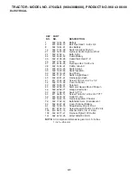
Page 31: ...34 532 11 07 12 Switch Light Reset 40 532 40 21 67 Harness Ign Dash 41 817 72 04 08 Screw Thd Cut 1 4 20 x 1 2 42 532 13 15 63 Cover Terminal 43 532 19 25 07 Solenoid 45 532 42 52 70 Ammeter Gauge Round Snap in 46 532 42 52 71 Gauge Hourmeter 50 532 17 46 51 Switch PTO 55 817 06 05 12 Screw Thdrol 5 16 18 x 3 4 TYTT 59 532 40 03 03 Outlet 12 Volt 71 532 19 42 76 Harness Ignition Chassis 79 532 17 ...

Page 32: ... 176 175 178 165 228 228 194 150 180 130 130 36 36 199 162 177 196 221 162 58 189 189 chassis tex_TEX GT HUSQ_50 298 238 3 189 189 152 5 181 176 137 137 176 176 14 214 202 203 204 210 25 207 211 209 212 205 206 208 15 234 52 217 68 68 213 213 218 68 68 68 68 183 183 236 236 34 235 235 18 130 130 ...

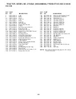
Page 33: ...Bushing Mtg Fender Crgo 182 532 40 68 59 Dash Lower 183 874 78 05 20 Bolt Fin Hex 5 16 18 unc x 1 1 4 189 817 00 05 12 Screw 5 16 18 x 3 4 NOTE All component dimensions given in U S inches 1 inch 25 4 mm KEY PART NO NO DESCRIPTION 194 873 90 05 00 Nut Lock Hex Flange 5 16 18 196 532 41 77 78 Console Asm Deck Lift 199 532 19 82 59 Plate Deck Lift 202 532 40 30 48 Vent Side Hood RH 203 532 40 30 76 ...

Page 34: ...8 208 210 211 211 166 17 161 35 167 160 160 203 163 214 125 215 222 56 197 196 15 29 159 153 153 159 15 116 73 2 145 3 7 9 69 33 2 145 1 33 69 3 121 286 114 125 125 125 80 213 221 160 206 26 207 209 92 125 116 drive tex_G700_pedal_2 48 190 189 50 51 52 51 51 187 49 49 186 99 70 74 220 74 ...

Page 35: ...73 80 05 00 Nut Lock Hex W Ins 5 16 18 unc 116 873 90 05 00 Nut Lock Hex Flange 5 16 18 121 532 17 56 11 Bracket Strap Torque 125 817 00 05 12 Screw 5 16 18 x 3 4 145 532 16 31 68 Washer Axle Flange 153 532 12 47 88 Retainer Spring 159 876 02 04 12 Pin Cotter 1 8 x 3 4 160 532 16 94 84 Retainer Clip 161 532 10 57 09 Spring Return Clutch 163 532 41 81 85 Rod Pedal Control 166 532 19 72 90 Nut Push ...

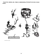
Page 36: ...36 91 1 12 11 41 42 85 29 30 2 ª 22 34 2ª 4 84 45 62 71 70 79 69 87 2 engine tex_bs 2cyl_25 18 15 9 90 28 37 37 TRACTOR MODEL NO 2754GLS 96043006600 PRODUCT NO 960 43 00 66 ENGINE ...

Page 37: ... 16 18 unc x 1 w Sems 90 817 00 06 16 Screw 3 8 16 x 1 91 532 18 74 95 Bushing 1 375 OD 116 532 42 46 59 Knob Soft Touch 117 532 42 08 28 Valve Fuel Reserve Engine Power Rating Information The gross power rating for individual gas engine models is labeled in accordance with SAE Society of Automotive Engineers code J11940 Small Engine Power Torque Rating Procedure and rating performance has been ob...

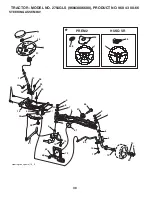
Page 38: ...96043006600 PRODUCT NO 960 43 00 66 STEERING ASSEMBLY 61 steering tex_special_13_r1 21 1 1 26 228 26 HUSQ SR PREM 2 35 19 60 59 58 63 5 62 15 14 13 13 53 8 70 68 69 16 28 28 13 22 64 4 15 14 6 9 8 7 9 8 7 67 67 66 6 2 45 51 63 57 ...

Page 39: ...6 12 Screw 3 8 16 x 3 4 35 532 19 47 32 Gear Sector Plate 45 819 18 38 12 Washer 9 16 x 2 3 8 x 12 Ga 51 873 94 08 00 Nut Hex Jam Toplock 1 2 20 unf 53 532 18 89 67 Washer Hardened 793 x 1 637 x 060 57 532 19 72 46 Bracket Upstop 58 532 19 47 47 Bolt Shoulder Sector Pivot CFM 59 532 19 47 48 Washer Thrust Sector Steering 60 873 97 10 00 Nut Flange Lock 5 8 11 61 532 19 47 40 Draglink LH 62 532 19 ...

Page 40: ...6 18 unc x 3 4 w Sems 10 532 19 69 77 Pan Seat 21 532 17 18 52 Bolt Shoulder 5 16 18 37 873 80 05 00 Nut Lock 5 16 18 unc 40 532 19 76 61 Handle Slide Seat 41 532 19 82 00 Spring Latch Seat 43 874 76 06 12 Bolt Fin Hex 3 8 16 unc x 3 4 44 819 13 38 12 Washer 13 32 x 2 3 8 x 12 Ga KEY PART NO NO DESCRIPTION KEY PART NO NO DESCRIPTION NOTE All component dimensions given in U S inches 1 inch 25 4 mm ...

Page 41: ...59 Bearing Flange Front Wheel Only 8 532 17 50 39 Cap Axle Front Wheel Only 9 532 17 04 53 Tire Rear 10 532 00 71 54 Tube Rear Service Item Only 11 532 14 45 10 Rim Assembly Rear 532 14 43 34 Sealant Tire 10 oz Tube 14 6 2 1 532 41 16 58 Decal Operator s 2 532 42 47 89 Decal Hood Emblem 3 532 41 86 00 Decal Pedal 4 532 42 55 42 Decal Replacement 6 532 41 84 97 Decal Engine HP 8 532 19 87 85 Decal ...

Page 42: ...7 7 49 46 32 33 31 30 1 33 52 52 43 196 97 33 192 49 34 39 185 46 46 6 21 122 114 98 31 32 25 26 24 27 58 60 59 21 21 194 113 49 187 190 184 190 187 50 120 117 116 21 197 21 197 21 197 197 197 189 21 18 21 21 18 18 18 21 13 14 15 11 8 29 mower_deck 54 tex_10_r1 12 16 19 241 242 ...

Page 43: ... Idler Stationary 43 532 19 60 65 Arm Idler 46 532 13 77 29 Screw Thdroll 1 4 20 x 5 8 47 532 19 61 03 V Belt Mower 49 873 90 06 00 Nut Lock Flg 3 8 16 unc 50 872 11 06 16 Bolt Rdhd Sqnk 3 8 16 unc x 2 52 532 19 73 79 Pulley Idler 4 50 58 532 18 73 42 Baffle Right 59 532 18 73 44 Baffle Left 60 532 18 76 07 Baffle Center 97 532 17 85 15 Washer Hardened 98 532 19 61 05 Spring Drive 113 872 11 05 08...

Page 44: ...10 532 19 63 14 Spring Torsion 87 532 19 42 09 Pin Cotter 7 16 Bow Tie Lock 88 532 19 53 04 Spring Lift Assist 89 819 19 19 12 Washer Clear Zinc KEY PART NO NO DESCRIPTION NOTE All component dimensions given in U S inches 1 inch 25 4 mm KEY PART NO NO DESCRIPTION 90 532 19 42 08 Pin Cotter 5 16 Bow Tie Lock 91 532 40 34 07 Link Lift Susp Mower Rear 97 817 00 06 12 Screw 3 8 16 x 75 98 532 19 52 64...

Page 45: ...46 SERVICE NOTES ...

Page 46: ...47 SERVICE NOTES ...

Page 47: ...ders Applies to units factory equipped with Roll Over Protection System 90 Days Commercial Walk Mowers includes 21 wide area 90 Days Commercial Turf Specialty Equipment 1 Year 1 Year 1 Year Zero Turn Commercial Turf Specialty Attachments 2 Years 1 Year 90 Days Power Cutters Lifetime Ignition Warranty Parts Only 1 Year 90 Days 1 Year K750 only 90 Days Automatic Mower 1 Year Battery Warranty 2 Years...

Page 48: ...r SECTION 4 EXCEPTIONS AND LIMITATIONS This warranty shall be inapplicable to defects resulting from the following 1 Accident abuse misuse negligence and neglect including stale fuel dirt abrasives moisture rust corrosion or any adverse reaction due to incorrect storage or use habits 2 Failure to operate or maintain the unit in accordance with the Owner s Operator s manual or instruction sheet fur...

Page 49: ...532 42 56 14 12 02 08 TH Printed in U S A ...

Reviews: