English
– 17
STARTING AND STOPPING
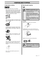
Check before starting
For safety reasons follow these recommendations!
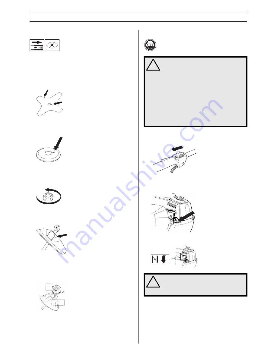
•
Check the blade to ensure that no cracks have formed at
the bottom of the teeth or by the centre hole. The most
common reason why cracks are formed is that sharp
corners have been formed at the bottom of the teeth while
sharpening or that the blade has been used with dull
teeth. Discard a blade if cracks are found.
•
Check that the support flange is not cracked due to fatigue
or due to being tightened too much. Discard the support
flange if it is cracked.
•
Ensure the locking nut has not lost its captive force. The
nut lock should have a locking force of at least 1.5 Nm.
The tightening torque of the locking nut should be 35-50
Nm.
•
Check that the blade guard is not damaged or cracked.
Replace the blade guard if it is exposed to impact or is
cracked.
•
Check that the trimmer head and trimmer guard are not
damaged or cracked. Replace the trimmer head or
trimmer guard if they have been exposed to impact or are
cracked.
•
Never use the machine without a guard nor with a
defective guard.
Starting and stopping
Starting
Ignition:
Set the stop switch to the start position.
Primer bulb:
Press the primer bulb repeatedly until fuel
begins to fill the bulb. The bulb need not be completely filled.
Choke:
Set the choke control in the choke position.
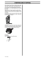
!
WARNING! The complete clutch cover and
shaft must be fitted before the machine is
started, otherwise the clutch can come loose
and cause personal injury.
Always move the machine away from the
refuelling area before starting. Place the
machine on a flat surface. Ensure the cutting
attachment cannot come into contact with
any object.
Make sure no unauthorised persons are in
the working area, otherwise there is a risk of
serious personal injury. The safety distance
is 15 metres.
!
WARNING! When the engine is started with
the choke in either the choke or start throttle
positions the cutting attachment will start to
rotate immediately.
Summary of Contents for 323RJ Series
Page 26: ......
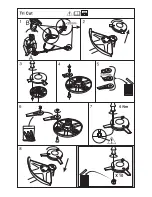
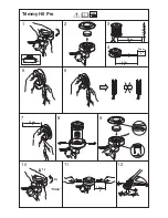
Page 27: ...1 Trimmy H II 2 3 4 5 6 7 8 9 7 5 m 25 2 0 2 4 mm 080 095 1 2 15 cm 6 3 7 m 12 15 cm 6 ...
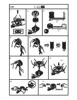
Page 30: ... Clic 1 2 3 5 6 7 10 11 8 5 m 28 4 8 4 2 m 14 2 4 2 7 mm 095 106 10 cm 4 6 15 cm S35 ...
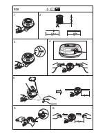
Page 31: ...1 2 4 3 2 4 2 7 mm 095 106 4 25 m 14 4 25 m 14 B 6 15 cm A 6 15 cm S35 5 ...
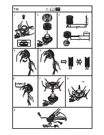
Page 32: ...T35 Clic 1 2 3 5 6 7 9 8 5 m 28 4 8 4 3 m 14 2 4 2 7 mm 095 106 10 cm 4 6 15 cm ...
Page 33: ......
Page 34: ... z H 5 z H 5 ...
Page 35: ......


