background image

20 – 

English

MAINTENANCE

Fine adjustment of the idle speed T

Adjust the idle speed using the idle adjustment screw T, if it is 
necessary to readjust. First turn the idle adjustment screw T 
clockwise until the cutting attachment starts to rotate. Then 
turn the screw anticlockwise until the cutting attachment 
stops. The idle speed is correctly adjusted when the engine 
will run smoothly in every position. The idle speed should also 
be well below the speed at which the cutting attachment starts 
to rotate.

IMPORTANT! If the idle speed cannot be adjusted so that the 
cutting attachment stops, contact your dealer/service 
workshop. Do not use the machine until it has been correctly 
adjusted or repaired.

High speed jet H

The high speed jet H affects the engine power, speed, 
temperature and fuel consumption. If the high speed jet H is 
set too lean (screwed in too far) the engine speed will be too 
high and cause engine damage. Do not let the engine run at 
full speed for more than 10 seconds.

Apply full throttle and turn the high speed jet H very slowly 
clockwise until the engine slows down. Then turn the high 
speed jet H very slowly anticlockwise until the engine starts to 
run unevenly. Now turn the high speed jet H slowly clockwise 
a little way until the engine runs smoothly. 

Note that the engine should not be under load when you 
adjust the high speed jet H. You should therefore remove the 
cutting attachment, nut, support flange and drive disc before 
adjusting the high speed jet H.

The high speed jet H is adjusted correctly when the machine 
burbles a little. If the machine races then the setting is too 
lean. If the engine produces a lot of smoke and burbles a lot 
then the setting is too rich.

CAUTION! For optimum adjustment of the carburettor, 
contact a qualified dealer/service workshop that has a 
revolution counter at their disposal. 

Correctly adjusted carburettor

When the carburettor is correctly adjusted the machine will 
accelerate without hesitation and burble a little at maximum 
speed. It is also important that the cutting attachment does 
not rotate at idle. If the low speed jet L is set too lean it may 
cause starting difficulties and poor acceleration.

If the high speed jet H is set too lean it will result in less power, 
less performance, poor acceleration and/or damage to the 
engine.

If both the L and H jets are set too rich it will results in 
acceleration problems or too low a working speed.

Muffler

CAUTION! 

 Some mufflers are fitted with a catalytic 

converter. See chapter on Technical data to see whether your 
machine is fitted with a catalytic converter.

The muffler is designed to reduce the noise level and to direct 
the exhaust gases away from the operator. The exhaust 
gases are hot and can contain sparks, which may cause fire 
if directed against dry and combustible material.

Some mufflers are equipped with a special spark arrestor 
mesh. If your machine has this type of muffler, you should 
clean the mesh at least once a week. This is best done with a 
wire brush.

On mufflers without a catalytic converter the mesh should be 
cleaned weekly, or replaced if necessary. On mufflers fitted 
with a catalytic converter the mesh should be checked, and if 
necessary cleaned, monthly. 

If the mesh is damaged it 

should be replaced.

If the mesh is frequently blocked, this can be a sign that the 
performance of the catalytic converter is impaired. Contact 
your dealer to inspect the muffler. A blocked mesh will cause 
the machine to overheat and result in damage to the cylinder 
and piston. See also instructions under the heading 
Maintenance.

CAUTION! 

 Never use a machine with a defective muffler.

H

!

WARNING! Mufflers fitted with catalytic 
converters get very hot during use and remain 
so for some time after stopping. This also 
applies at idle speed. Contact can result in 
burns to the skin. Remember the risk of fire!

Summary of Contents for 323RJ Series

Page 1: ...E E En n n ng g g gl l l li i i is s s sh h h h 323RJ 325RJX series Operator s manual EPA Please read the operator s manual carefully and make sure you understand the instructions before using the machine ...

Page 2: ... metres Machines fitted with saw blades or grass blades can be thrown violently to the side when the blade comes into contact with a fixed object The blade is capable of amputating an arm or leg Always keep people and animals at least 15 metres from the machine Arrows which show limits for handle positioning Always wear approved protective gloves Wear sturdy non slip boots Only use non metallic fl...

Page 3: ...0 Basic working techniques 10 WHAT IS WHAT What is what on the trimmer 12 ASSEMBLY Fitting the J handle 13 Fitting blades and trimmer heads 13 Fitting a trimmer guard and Superauto II 1 trimmer head 13 Fitting the blade guard combination guard grass blade and grass cutter 14 Fitting other guards and cutting attachments 14 FUEL HANDLING Fuel 15 Fuelling 16 STARTING AND STOPPING Check before startin...

Page 4: ...When you press the lock A i e when you grasp the handle it releases the throttle control B When you release the handle the throttle control and the throttle lock both move back to their original positions This movement is controlled by two independent return springs This arrangement means that the throttle control is automatically locked at the idle setting Stop switch Use the stop switch to switc...

Page 5: ...ades and grass cutters are intended for cutting coarse grass A trimmer head is intended for trimming grass Locking nut A locking nut is used to secure some types of cutting attachment WARNING Overexposure to vibration can lead to circulatory damage or nerve damage in people who have impaired circulation Contact your doctor if you experience symptoms of overexposure to vibration These symptoms incl...

Page 6: ...re the engine stops when you move the stop switch to the stop setting Cutting attachment guard Ensure that the guard is undamaged and is not cracked Replace the guard if it has been exposed to impact or is cracked Always use the recommended guard for the cutting attachment you are using See chapter on Technical data Vibration damping system Regularly check the vibration damping units for cracks or...

Page 7: ... file gauge An incorrectly sharpened or damaged blade increases the risk of accidents 3 Check the cutting attachment for damage or cracks A damaged cutting attachment should always be replaced Locking nut When fitting tighten the nut in the opposite direction to the direction of rotation of the cutting attachment To remove it undo the nut in the same direction as the cutting attachment rotates CAU...

Page 8: ...he correct length To increase the life of the cord it can be soaked in water for a couple of days This will make the line tougher so that it lasts longer IMPORTANT This section describes how to choose and maintain your cutting equipment in order to Reduce the risk of blade thrust Obtain maximum cutting performance Extend the life of cutting equipment Only use cutting attachments with the guards we...

Page 9: ...trical relays switches or boilers When storing and transporting fuel always use approved containers intended for this purpose When storing the machine for long periods the fuel tank must be emptied Contact your local gas station to find out where to dispose of excess fuel IMPORTANT The machine is only designed for trimming grass grass clearing and or forestry clearing The only accessories you can ...

Page 10: ... for example along verges or around trees Grass clearing using a grass blade A grass blade is used for all types of tall or coarse grass The grass is cut down with a sideways swinging movement where the movement from right to left is the clearing stroke and the movement from left to right is the return stroke Let the left hand side of the blade between 8 and 12 o clock do the cutting If the blade ...

Page 11: ...normal lawn mower Keep the cord parallel to the ground when cutting Avoid pressing the trimmer head against the ground as this can ruin the lawn and damage the tool Do not allow the trimmer head to constantly come into contact with the ground during normal cutting Constant contact of this type can cause damage and wear to the trimmer head Sweeping The fan effect of the rotating cord can be used fo...

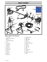
Page 12: ...7 Throttle control 8 Stop switch 9 Throttle lock 10 Cylinder cover 11 Starter handle 12 Fuel tank 13 Choke control 14 Air purge 15 Air filter cover 16 Handle adjustment 17 Locking nut 18 Support flange 19 Drive disc 20 Socket spanner 21 Operator s manual EPA 22 Allen key 23 Locking pin 24 Support cup 25 Blade 26 Transport guard 27 J handle 28 Support eyes for harness 29 Harness ...

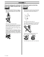
Page 13: ... the shaft To fit the trimmer head first separate the two halves see diagram Proceed as follows Insert a finger into the centre hole of the cover I while grasping the cover with your other fingers Using the index finger and thumb of your other hand release the two catches J that engage in the cut outs in the bottom half K Pull apart the trimmer head grasping the cover firmly Place the cover I and ...

Page 14: ...e the socket spanner in the tool kit Hold the shaft of the spanner as close to the blade guard as possible To tighten the nut turn the spanner in the opposite direction to the direction of rotation Caution left hand thread Fitting other guards and cutting attachments Fit the correct trimmer guard A for use with the trimmer head Hook the trimmer guard combination guard onto the fitting on the shaft...

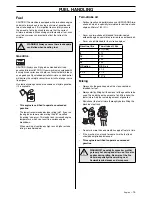
Page 15: ...ntinuous high revs a higher octane rating is recommended Two stroke oil For best results and performance use HUSQVARNA two stroke oil which is specially formulated for our two stroke engines Mixture 1 50 2 Never use two stroke oil intended for water cooled outboard engines sometimes referred to as outboard oil Never use oil intended for four stroke engines Mixing Always mix the gasoline and oil in...

Page 16: ...the following precautions will lessen the risk of fire Do not smoke or place hot objects near fuel Always shut off the engine before refuelling Always stop the engine and let it cool for a few minutes before refuelling When refuelling open the fuel cap slowly so that any excess pressure is released gently Tighten the fuel cap carefully after refuelling Always move the machine away from the refuell...

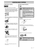
Page 17: ...nd trimmer guard are not damaged or cracked Replace the trimmer head or trimmer guard if they have been exposed to impact or are cracked Never use the machine without a guard nor with a defective guard Starting and stopping Starting Ignition Set the stop switch to the start position Primer bulb Press the primer bulb repeatedly until fuel begins to fill the bulb The bulb need not be completely fill...

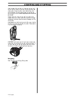
Page 18: ...ts When the engine starts return choke control to run position and apply full throttle the throttle will automatically disengage from the start setting CAUTION Do not pull the starter cord all the way out and do not let go of the starter handle when the cord is fully extended This can damage the machine CAUTION Do not put any part of your body in marked area Contact can result in burns to the skin...

Page 19: ...rried out by a skilled technician CAUTION If the cutting attachment rotates when the engine is idling the idle adjustment screw T should be turned anti clockwise until the cutting attachment stops Rec idle speed 2700 rpm Recommended max speed See the Technical data section Fine adjustment When the machine has been run in the carburettor should be finely adjusted The fine adjustment should be carri...

Page 20: ...n counter at their disposal Correctly adjusted carburettor When the carburettor is correctly adjusted the machine will accelerate without hesitation and burble a little at maximum speed It is also important that the cutting attachment does not rotate at idle If the low speed jet L is set too lean it may cause starting difficulties and poor acceleration If the high speed jet H is set too lean it wi...

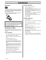
Page 21: ... spark plug can damage the piston cylinder Air filter The air filter must be regularly cleaned to remove dust and dirt in order to avoid Carburettor malfunctions Starting problems Loss of engine power Unnecessary wear to engine parts Excessive fuel consumption Clean the filter every 25 hours or more regularly if conditions are exceptionally dusty Cleaning the air filter Remove the air filter cover...

Page 22: ...hat hold the bevel gear are tight Check that there are no fuel leaks from the engine tank or fuel lines Weekly maintenance Check the starter and starter cord Clean the carburettor area Clean the outside of the spark plug Remove it and check the electrode gap Adjust the gap to 0 5 mm 20 or replace the spark plug Check that the spark plug is fitted with a suppressor Clean the cooling fins on the cyl...

Page 23: ...ode gap inch mm 0 02 0 5 0 02 0 5 Fuel and lubrication system Manufacturer type of carburettor Zama C1Q Zama C1Q Fuel tank capacity US pint litre 1 06 0 5 1 06 0 5 Weight Weight without fuel cutting attachment and guard Lbs kg 9 3 4 2 9 5 4 3 Sound levels see note 1 Equivalent sound pressure level at the user s ear measured according to ANSI B175 3 1997 dB A min max 90 97 92 98 Vibration levels Vi...

Page 24: ...each subsequent purchaser that the engine is free from defects in materials and workmanship which cause the failure of a warranted part for a period of two years WHAT IS COVERED REPAIR OR REPLACEMENT OF PARTS Repair or replacement of any warranted part will be performed at no charge to the owner at an approved Husqvarna Forest Garden servicing dealer If you have any questions regarding your warran...

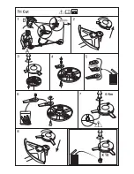
Page 25: ...1 Super Auto II Super Auto II 1 2 3 4 5 6 7 8 9 10 4 0 m 13 2 4 mm 095 2 0 m 6 5 6 6 15 cm 15 cm ...

Page 26: ......

Page 27: ...1 Trimmy H II 2 3 4 5 6 7 8 9 7 5 m 25 2 0 2 4 mm 080 095 1 2 15 cm 6 3 7 m 12 15 cm 6 ...

Page 28: ...1 Trimmy Hit 2 3 4 5 6 7 8 9 10 11 Click Click 7 0 m 23 12 cm 5 3 5 m 11 15 cm 6 2 0 2 4 mm 080 095 15 cm 6 ...

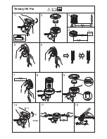
Page 29: ...1 Trimmy Hit Pro 2 5 6 7 8 9 10 12 Click 3 4 7 5 m 25 2 0 2 4 mm 080 095 15 cm 6 3 7 m 12 1 2 11 15 cm 6 15 cm 6 ...

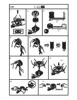
Page 30: ... Clic 1 2 3 5 6 7 10 11 8 5 m 28 4 8 4 2 m 14 2 4 2 7 mm 095 106 10 cm 4 6 15 cm S35 ...

Page 31: ...1 2 4 3 2 4 2 7 mm 095 106 4 25 m 14 4 25 m 14 B 6 15 cm A 6 15 cm S35 5 ...

Page 32: ...T35 Clic 1 2 3 5 6 7 9 8 5 m 28 4 8 4 3 m 14 2 4 2 7 mm 095 106 10 cm 4 6 15 cm ...

Page 33: ......

Page 34: ... z H 5 z H 5 ...

Page 35: ......

Page 36: ... z H 5 2004 03 25 z H 5 1140270 95 ...

Reviews: