22
3
Fuel system
A
Throttle
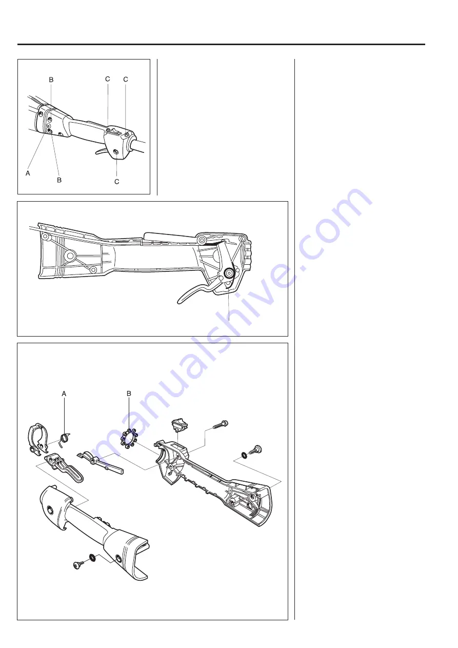
Pull away the shaft with the throttle
from the clutch cover.
Remove the throttle from the shaft.
Throttle
Remove both screws (A) (one on each
side).
Remove the screws (B) and pull away
the shaft with the throttle from the
clutch cover.
Loosen the 3 front screws (C) (approx.
2 turns) holding the throttle halves and
pull the throttle off of the shaft.
Assembly of the throttle is done in the
reverse order as set out for disman-
tling.
Position the parts in the left-hand
throttle half.
Ensure the return spring (A) is facing
the right way.
Check that the throttle cable and the
short-circuit cable are pressed correctly
down in their channels so that they are
not pinched when the two throttle
halves are screwed together.
Do not forget to put the vibration
element (B) in position before the
throttle halves are put together. Lubri-
cate the vibration element with soapy
water. This facilitates fitting the throttle
on the shaft.
Fit together the throttle halves using
the 5 screws, but do not tighten them
fully before the throttle has been
positioned on the shaft.
Assemble the remaining parts in the
reverse order as set out for dis-
mantling.
Remove the screws holding the throttle
together and carefully separate the
halves.
Note how the different parts are fitted.
Pay special attention to which way the
return spring (A) faces.
The stop contacts can be pried back
using a small screwdriver if they need
to be replaced.
Summary of Contents for 324HDA
Page 1: ...Workshop manual 324LX 324RX 324HDA English ...
Page 25: ...24 3 Fuel system ...
Page 33: ...32 5 Angle gear ...
Page 45: ...44 7 Piston crankshaft and crankcase ...
Page 49: ...2004W26 114 02 94 26 ...


