38
6
Cylinder block and valve mechanism
2
1
Dismantle the crankshaft and the cam
belt.
Pull away the sealing rings from the
crankshaft .
Lift up the crankcase and pull the piston
out of the cylinder bore.
NOTE!
Note the cam belt’s direction of
rotation (for example, from which
direction the text on the belt can
be read) so it rotates in the same
direction when reassembled.
Pull away the sealing rings from the
crankshaft .
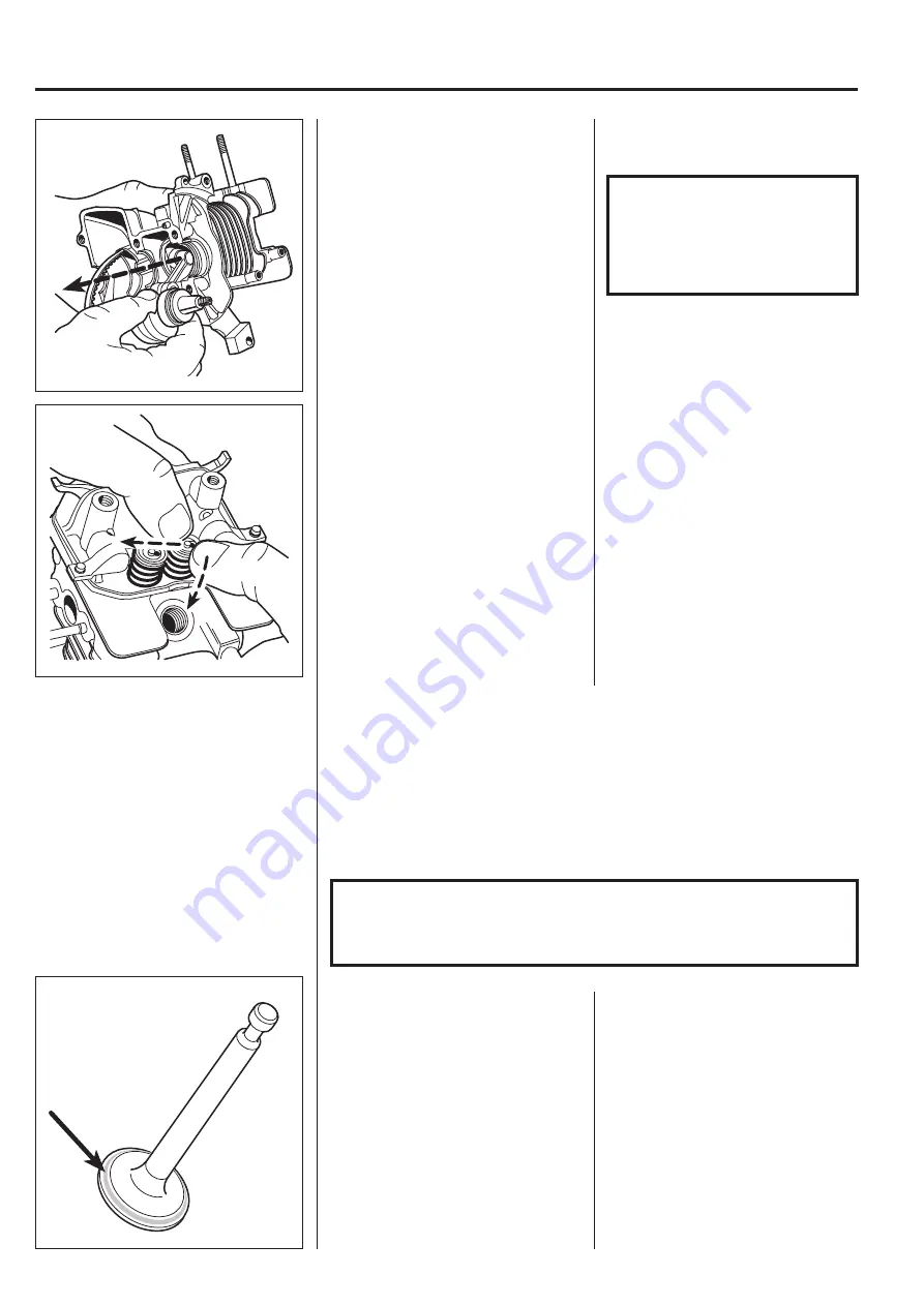
Dismantle the valves.
Press together the spring with your
thumbs and remove the valve disc.
Lift out the valve spring and the valve.
Check the component parts with regard
to damage and wear.
Dismantle the valves.
Insert a rolled-up cloth in the cylinder
bore to support the valves when
dismantling the valve discs.
Press down valve disc with your
thumbs and move it to the adjacent cut-
out.
Lift out the disc, valve spring and valve.
Standard dimensions, wear tolerances
Component
Standard
Wear limit
Valve spring length
20.66 mm
20.00 mm
Valve spindle diameter, exhaust
3.435 – 3.450 mm
3.380 mm
Valve spindle diameter, inlet
3.470 – 3.485 mm
3.400 mm
Valve guide inner diameter
3.500 – 3.518 mm
3.560 mm
Clearance, valve spindle/valve guide, exhaust
0.050 – 0.083 mm
0.120 mm
Clearance, valve spindle/valve guide, inlet
0.015 – 0.048 mm
0.098 mm
Timing gear inner diameter
4.020 – 4.050 mm
4.100 mm
Cam height
22.097 mm
21.797 mm
NOTE!
When the valve guides are worn in excess of the wear tolerances these
cannot be changed separately but the entire cylinder block must be
replaced with a new one.
Clean the valves and grind them in
using valve grinding compound.
Clean the valves thoroughly before
assembling.
The valves are marked:
HI = inlet valve
HE = exhaust valve
Clean off any deposits from the valves
(especially the exhaust valve) using a
wire brush.
Check the valve head for signs of
cracking.
Small unevenness can be ground away
using valve grinding compound.
Apply a thin layer of bearing paste on
the valve head. Insert the valve in the
guide and rotate it back and forth.
Repeat the procedure until a matt, grey,
unbroken stripe (approximately 0.8 mm
wide) is visible around the head and
valve seating.
Clean the valves thoroughly before
assembling.
Summary of Contents for 324HDA
Page 1: ...Workshop manual 324LX 324RX 324HDA English ...
Page 25: ...24 3 Fuel system ...
Page 33: ...32 5 Angle gear ...
Page 45: ...44 7 Piston crankshaft and crankcase ...
Page 49: ...2004W26 114 02 94 26 ...


