background image

14

 – English

ASSEMBLY

It is extremely important
that the disc drive’s/support
flange’s guide engages
correctly in the cutting
equipment’s centre hole
when assembling the cutting
equipment. Cutting
equipment assembled
incorrectly can result in
serious and/or fatal personal
injury.

!

WARNING!
Under no circumstances may the cutting
equipment be used without an approved
guard fitted. See the chapter 

“Technical

data”. If the wrong guard or a defective
guard is fitted this can cause serious
personal injury.

• Clip the loop handle onto

the shaft. Note that the
loop handle must be
fitted between the arrows
on the shaft.

• Slide the spacer into the

slot in the loop handle.

• Fit the nut, knob and

bolt. Do not overtighten.

• Attach the J-handle to the

loop handle using the
three screws, as shown.

• Now adjust the trimmer

to give a comfortable
working position. Tighten
the bolt/knob.

Assembling the J-handle

!

WARNING
Only grass blades or trimmer heads/
plastic blades may be used when the J-
handle is fitted. Clearing blades must
never be used with the J-handle.

Assembling the spray guard and
trimmer head Superauto II

• Fit the guard (A) intended

for use with the trimmer
head. Hook the guard onto
the shaft fitting and secure
it with the bolt (L).

• Fit the drive disc (B) on the

output axle.

• Turn the blade axle until

one of the holes in the
drive disc aligns with the
hole in the gear housing.

• Insert the locking pin (C)

in the hole so that the axle
is locked.

• The trimmer head must be

split to be fitted (see the
diagram). Proceed as
follows:

• Insert your finger into the

centre hole of the cover (I)
at the same time as you
hold the cover with your
other fingers. Press the two
catches (J) that extend from
the cut-out on the bottom
section (K) using the
thumb and index finger of
your other hand. Press
apart the trimmer head
using the fingers on the
cover.

• Place the cover (I) and the

support flange (F) on the
output axle.

• Fit the nut (G). The

tightening torque of the
nut is 35-50 Nm (3,5-5
kpm). Use the socket
spanner in the tool kit.
Hold the handle of the
spanner as close to the
trimmer guard as possible.
The nut is tightened when
the spanner is turned
against the direction of
rotation (left-hand thread).

• Fit the trimmer head‘s

bottom section (K) on the
cover (I) by pressing the
two sections together with

K

J

I

G

F

I

A

K

B

C

the cut-outs on the bottom section aligned with the catches
on the cover.

• To dismantle follow the instructions in the reverse order.

Assembly of the blade and trimmer
head

Summary of Contents for 325RJX Series

Page 1: ...101 91 73 26 325RJ X SERIES Operator s manual Read through the Operator s manual carefully and understand the content before using the machine ...

Page 2: ...ax speed of output axle rpm This product is in accordance with applicable CE directives Beware of thrown objects and ricochets 50FT 15 m 50FT 15 m Only use non metallic flexible cutting elements that is trimmer head with trimmer cord Use anti slip and stable boots Always wear approved protective gloves Only intended for the trimmer head The operator of the machine shall ensure while working that n...

Page 3: ...ard grass blade and grass knife 15 Assembling other guards and cutting equipment 15 FUEL HANDLING Fuel mixture 16 Fuelling 16 START AND STOP Control before starting 17 Start and stop 17 MAINTENANCE Carburettor 18 Muffler 20 Cooling system 20 Spark plug 20 Air filter 21 Angle gear 21 Maintenance schedule 21 TECHNICAL DATA 325RJ X 23 WARNING Under no circumstances may the design of the machine be mo...

Page 4: ...rrectly or carelessly can become a dangerous tool that can cause serious or fatal injury to the operator or others It is extremely important that you read and understand the content of this manual When using a trimmer personal protective equipment approved by the appropriate authorities must be used Personal protective equipment does not eliminate the risk of accidents however it can reduce the ef...

Page 5: ...oblems Seek medical attention if you experience physical symptoms that can be related to over exposure to vibrations Examples of such symptoms are numbness lack of feeling tickling pricking pain lack of or a reduction in normal strength changes in the colour of the skin or its surfaces These symptoms normally appear in the fingers hands or wrists 3 Cutting attachment guard This guard is intended t...

Page 6: ... see the section Control maintenance and service of the machine s safety equipment WARNING Mufflers fitted with catalytic converters become extremely hot during use and after stopping This also applies at idling speeds Contact can result in burns to the skin Be observant to the risk of fire WARNING Bear in mind that exhaust fumes contain carbon monoxide which can cause carbon monoxide poisoning Th...

Page 7: ...ess in the throttle trigger lock and make sure it returns to its original position when released Ensure that the throttle and throttle trigger lock move easily and that their return spring systems function See section Start Start the machine and apply full throttle Release the throttle and check that the cutting equipment stops and remains at a standstill If the cutting equipment rotates with the ...

Page 8: ...quipment should be maintained as described in this section If your machine does not meet any of these controls you should contact your service workshop 6 Cutting equipment This section describes how through correct maintenance and through using the right type of cutting equipment you can Reduce the machine s tendency to kickback Obtain maximum cutting capacity Increase the service life of the cutt...

Page 9: ...ues to rotate even after the throttle has been released Ensure that the cutting equipment has stopped completely and remove the cable from the spark plug before you start to work on it IMPORTANT INFORMATION Always ensure the trimmer cord is wound tightly and evenly around the drum otherwise harmful vibrations will occur IMPORTANT INFORMATION The section describes how through correct maintenance an...

Page 10: ...uipment See the section Personal protective equipment Never use a machine that has been modified so that it no longer corresponds with the original design Never use a machine that is faulty Follow the maintenance control and service instructions in this Operator s Manual Some maintenance and service actions should be carried out by trained and qualified specialists See the chapter Maintenance All ...

Page 11: ...ues Always drop to idling speed after each working operation Longer periods running at full throttle without loading the engine that is without resistance which the engine feels from the cutting equipment when trimming can lead to serious engine damage Designations Brush cutting is a general term for clearing grass Grass blades are used for this purpose Grass trimming is a general term for light c...

Page 12: ...nd of the cord that carries out the work Let the cord work at its own pace Do not press the cord into the area to be cut The cord can easily remove grass and weeds up against walls fences trees and borders however it can also damage sensitive bark on trees and bushes and damage fence posts Reduce the risk of damaging plants by shortening the cord to 10 12 cm and reducing the engine speed Clearing ...

Page 13: ...h 9 Throttle trigger lock 10 Cylinder cover 11 Starter handle 12 Fuel tank 13 Choke 14 Air purge 15 Air filter cover 16 Clutch cover 17 Handlebar adjustment 18 Locking nut 19 Support flange 20 Drive disc 21 Socket spanner 22 Operator s Manual 23 Allen key 24 Locking pin 25 Support cup 26 Blade 27 Transport guard 28 J handle 29 Hanging ring 30 Harness 28 29 30 27 ...

Page 14: ... use with the trimmer head Hook the guard onto the shaft fitting and secure it with the bolt L Fit the drive disc B on the output axle Turn the blade axle until one of the holes in the drive disc aligns with the hole in the gear housing Insert the locking pin C in the hole so that the axle is locked The trimmer head must be split to be fitted see the diagram Proceed as follows Insert your finger i...

Page 15: ...combination guard grass blade and grass knife Hook the guard A onto the bracket on the shaft and secure with 1 bolt NOTE Use the recommended blade guard See Technical data Fit the drive disc B on the output axle Turn the blade axle until one of the holes in the drive disc aligns with the hole in the gear housing Insert the locking pin C in the hole so that the axle is locked Place the blade D supp...

Page 16: ...talytic converter muffler gets very hot during and after use This also applies during idling Be aware of the fire hazard especially when handling the saw near flammable substances or vapours Fuelling WARNING The following precautions reduce the risk of fire Do not smoke or place any sources of heat in the vicinity of the fuel Never refuel when the engine is running Always stop the engine and let i...

Page 17: ...l in the choke position AIR PURGE Press the air purge diaphragm repeatedly until fuel begins to fill the diaphragm The diaphragm need not be completely filled Warm engine Use the same starting procedure as for the cold engine but do not set the choke control in the choke position The start throttle position is obtained by setting the choke control in the choke position and then returning it to its...

Page 18: ...ling speed Fine adjustment When the machine has been run in the carburettor should be finely adjusted The fine adjustment should be carried out by qualified person First adjust the L jet then the idling screw T and then the H jet Conditions Before any adjustments are made the airfilter should be clean and the airfilter cover fitted Adjusting the carburettor while a dirty airfilter is in use will r...

Page 19: ... idle speed adjusting screw T clockwise until the cutting attachment starts to rotate move Then turn counter clockwise until the cutting attachment stops A correctly adjusted idle speed setting occurs when the engine runs smoothly in every position It should also be good margin to the rpm when the cutting attachment starts to rotate move CAUTION Contact your servicing dealer if the idle speed sett...

Page 20: ...gn that the function of the catalytic converter is impaired Contact your dealer to inspect the muffler A blocked screen will cause the engine to overheat resulting in damage to the cylinder and piston Also see under Maintenance NOTE Never use a machine with a defective muffler WARNING Mufflers fitted with catalytic converters become extremely hot during use and after stopping This also applies at ...

Page 21: ...cial grease Normally the grease does not need to be changed except when repairs are carried out Air filter The air filter should be cleaned regularly removing dust and dirt to avoid carburettor malfunction starting problems reduced engine power unnecessary wear to engine parts abnormal fuel consumption Clean the filter after every 25 hours or more regularly if operating conditions are exceptionall...

Page 22: ...ling fins on the cylinder and check that the air intake in the starter unit is not blocked 8 Check that the angle gear is 3 4 filled with grease Fill if necessary using special grease 1 3 4 5 6 8 7 Monthly maintenance 1 Clean the fuel tank 2 Clean the carburettor and the area surrounding it 3 Clean the fan and the area around it 4 Check the fuel filter and the fuel pipe replace if necessary 5 Chec...

Page 23: ...Fuel lubrication system Manufacturer type of carburettor Fuel tank capacity US pint litres Weight Weight without fuel cutting tool and guard Lbs kg Noise levels Equivalent noise pressure level at the user s ear measured according to EN 31806 and ISO 7917 dB A min max Equivalent noise power level at the user s ear measured according to EN 31806 and ISO 10884 dB A min max Vibration levels Vibration ...

Page 24: ...agnetic compatibility 89 336 EEC and applicable supplements The following standards have been applied EN292 2 EN ISO 11806 SMP Svensk Maskinprovning AB Fyrisborgsgatan 3 S 754 50 Uppsala Sweden has carried out voluntary type approval for Husqvarna AB The certificates are numbered SEC 98 631 325RJ X Huskvarna 25 November 1999 Bo Andréasson Development manager TECHNICAL DATA Approved accessories Thr...

Page 25: ...English 25 1 Super Auto II Super Auto II 1 2 3 4 5 6 7 8 9 10 4 0 m 13 2 4 mm 095 2 0 m 6 5 6 6 15 cm 15 cm ...

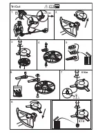
Page 26: ...1 Tri Cut 2 3 4 5 6 7 8 20mm 20mm B A 6 Nm X 10 ...

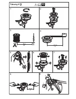
Page 27: ...English 27 1 Trimmy H II 2 3 4 5 6 7 8 9 7 5 m 25 2 0 2 4 mm 080 095 1 2 15 cm 6 3 7 m 12 15 cm 6 ...

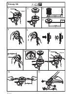
Page 28: ...28 English 1 Trimmy Hit 2 3 4 5 6 7 8 9 10 11 Click Click 7 0 m 23 12 cm 5 3 5 m 11 15 cm 6 2 0 2 4 mm 080 095 15 cm 6 ...

Page 29: ...English 29 1 Trimmy Hit Junior 2 5 6 7 8 9 10 12 Click 3 4 5 75 m 19 2 0 2 4 mm 080 095 15 cm 6 2 8 m 9 1 2 11 15 cm 6 15 cm 6 ...

Page 30: ...30 English 1 Trimmy Hit Pro 2 5 6 7 8 9 10 12 Click 3 4 7 5 m 25 2 0 2 4 mm 080 095 15 cm 6 3 7 m 12 1 2 11 15 cm 6 15 cm 6 ...

Page 31: ...English 31 1 Trimmy Hit VI 2 5 6 3 4 7 8 9 10 11 Click 7 0 m 23 12 cm 5 3 5 m 11 15 cm 6 2 0 2 4 mm 080 095 15 cm 6 ...

Page 32: ...32 English 1 2 3 4 5 6 7 8 9 35 50 NM 15 cm 6 Clic 3 5 m 11 7 0 m 23 2 4 3 3 mm 095 130 12 cm 5 Trimmy SII ...

Page 33: ... 15 cm 6 N 15 cm 6 502 25 56 01 502 26 04 01 502 25 53 01 502 26 24 01 x2 740 43 14 00 502 25 52 01 502 26 01 01 735 31 19 00 729 53 27 71 x3 738 21 03 04 502 26 03 01 502 27 07 01 502 26 86 01 1 2 3 4 Trimmy SII ...

Page 34: ...34 English 31 6E ...

Page 35: ...English 35 ...

Page 36: ...2001W17 31 6E ...

Reviews: