2
Electrical system
502 51 34-02
502 51 49-01
502 51 49-01
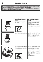
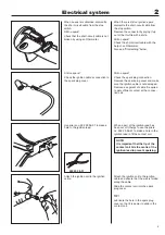
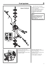
Remove the nut holding the flywheel.
Remove the nut holding the flywheel.
Fit the puller on the flywheel. Loosen
and remove the nut.
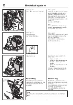
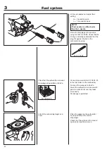
Assemble the ignition module.
Adjust the air gap. It should be 0.3 mm
between the permanent magnets in the
flywheel and the ignition module.
Tighten the screws and do not forget
the ring cable lug under the outer
screw.
Assemble other parts in the reverse
order as set out for dismantling.
NOTE!
Do not forget the rubber bushings between the fuel tank and the crankcase/
clutch cover and the fuel tank and starter.
NOTE!
The completely flat side on the
clutch should rest against the
washer closest to the flywheel.
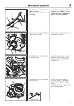
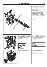
Remove the flywheel.
Dismantle the flywheel from the
crankcase using the puller
no. 502 51 49-01.
Gently knock the puller screw with a
hammer, if the flywheel sits tightly on
the crankshaft.
Assembly
Check that the cast key in the flywheel
and key way in the crankshaft are
undamaged.
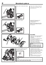
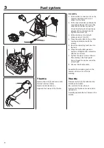
Fit the flywheel and centrifugal clutch.
Do not forget the washers (A).
Note the slots on the washer lie closest
to the flywheel. Align with the
equivalent pins on the flywheel.
Assemble the ignition module and
adjust the air gap to 0.3 mm.
Summary of Contents for 333R
Page 1: ...Workshop manual 333R 335R English ...
Page 2: ......
Page 36: ...34 4 Centrifugal clutch ...
Page 40: ...38 5 Angle gear ...
Page 50: ...48 6 Cylinder and piston ...
Page 60: ......
Page 61: ......
Page 62: ...2005W23 115 00 92 26 ...


