background image

34

4

Centrifugal clutch

Summary of Contents for 333R

Page 1: ...Workshop manual 333R 335R English ...

Page 2: ......

Page 3: ..._______________________________ 3 2 Electrical system ___________________________ 7 3 Fuel system______________________________ 13 4 Centrifugal clutch _________________________ 29 5 Angle gear_______________________________ 35 6 Cylinder and piston ________________________ 39 7 Crankshaft and crankcase __________________ 49 8 Tools ___________________________________ 55 ...

Page 4: ...g that has been dismantled The sensitive sealing lip can easily be damaged resulting in inferior sealing capacity Surfaces which the seal shall seal against must also be completely undamaged Lubricate the sealing lip with grease before it is fitted and ensure that it is not damaged e g by shoulders and splines on a shaft Use tape or a conical sleeve as protection It is important that the sealing r...

Page 5: ...3 1 Starter 1 Starter Contents Dismantling ___________________________________ 4 Assembly ____________________________________ 5 Replacing the drive dogs ________________________ 6 ...

Page 6: ...t the starter can be lifted out The cylinder cover does not need to be loosened or detached NOTE Ensure the bushings that guide the starter towards the fuel tank are not lost Remove the bolt in the centre of the starter pulley and remove the starter pulley Remove the bolt in the centre of the starter pulley Lift the starter pulley carefully from the starter cover Loosen the spring tension Loosen t...

Page 7: ...plied pre assembled and are fitted in the starter housing as a single unit Exercise care when opening the packaging so that the spring does not fly out Assemble the starter pulley Assemble a new starter cord NOTE A new starter cord can be fitted without the need of dismantling the starter Assemble the starter handle Assemble the starter handle Tie a double knot and fold under the free end Pull the...

Page 8: ... Remove the circlip and replace any damaged drive dogs or springs if necessary Remove the circlip holdings the drive dog Lift out the drive dog and spring for replacement Assemble in the reverse order as set out for dismantling Check that the drive dogs move easily Replacing the drive dogs Dismantle the drive body Replacing the drive dogs Fit the puller 502 51 49 01 on the flywheel see chapter 2 E...

Page 9: ...7 2 Electrical system 2 Electrical system Contents Checking the ignition spark __________________ 8 Dismantling ______________________________ 10 Assembly _______________________________ 12 ...

Page 10: ...eck the electrode gap It should be 0 5 mm Adjust the gap as needed to the correct value with the side electrode If the electrodes are worn more than 50 the spark plug should be changed If the electrodes are worn more than 50 the spark plug should be changed Too large a spark gap entails a great deal of stress on the ignition module and risk for short circuiting Check if a spark occurs when attempt...

Page 11: ...tion Remove the spark plug cover and make sure the ignition cable is not damaged Remove a segment of cable if required to get sufficient contact at the connec tion coil Use pliers no 502 50 06 01 to make a hole in the ignition lead When a part of the ignition lead has been cut off it helps to use the pliers no 502 50 06 01 to make a hole in the ignition lead to fit the contact coil NOTE It is impo...

Page 12: ... in order to easily check if cable breakage has occurred due to pinching for example Adjust the air gap Adjust the air gap as needed to the correct value Loosen the bolts Position the feeler gauge and press the ignition module against the flywheel Tighten the bolts and check the air gap again If the spark plug still does not fire the ignition system should be replaced Dismantling Dismantle the sta...

Page 13: ...swing the engine body to one side Remove the 3 screws E and swing the engine body to one side Dismantle the short circuit cable from the ignition module Dismantle the short circuit cable from the ignition module by removing the screw F and prying off the flat pin connector G Dismantle the ignition module and the centrifugal clutch Remove the remaining screws A holding the ignition module and both ...

Page 14: ... bushings between the fuel tank and the crankcase clutch cover and the fuel tank and starter NOTE The completely flat side on the clutch should rest against the washer closest to the flywheel Remove the flywheel Dismantle the flywheel from the crankcase using the puller no 502 51 49 01 Gently knock the puller screw with a hammer if the flywheel sits tightly on the crankshaft Assembly Check that th...

Page 15: ..._______ 15 Fuel filter __________________________________ 15 Fuel pump _________________________________ 16 Carburettor ________________________________ 16 Throttle ___________________________________ 24 Start throttle speed __________________________ 25 Carburettor settings _________________________ 26 Fuel system ...

Page 16: ...air filter and clean it in warm soapy water A damaged filter should be replaced with a new filter Air filter Dismantle the air filter cowling by loosening the quick clasps and lift off the air filter The filter is manufactured of foamed plastic and should be cleaned in tepid soapy water A damaged filter should be replaced with a new filter WARNING Do not clean not the filter with petrol Hazardous ...

Page 17: ... flat surface on the cover D is turned towards the diaphragm NOTE There is a small slit F in the diaphragm B that becomes visible when you carefully pull the edges of the diaphragm Check that the edges of the slit are not damaged Replace diaphragm if necessary Tank venting Check that the tank venting valve works correctly Replace the fuel cap if the valve is faulty Fuel filter The fuel filter can ...

Page 18: ... pump facilitates cold starts The pump cannot be repaired and must be replaced if it stops working Note how the fuel hoses are connected to simplify assembly Fuel pump The fuel pump has the task of facilitating the start of the engine when cold The pump fills the carburettor with fuel before attempting to start the engine This also prevents vapour bubbles from blocking the narrow fuel channels If ...

Page 19: ...red Dismantling the carburettor Carefully remove the control diaphragm A and gasket B Check the diaphragm for holes and wear on the pin C Replace the diaphragm if required The pump unit Pumps fuel from the tank to the carburettor The pump unit This is where the pump diaphragm E that pumps fuel from the tank to the carburettor s measuring unit is found The diaphragm is affected by pressure variatio...

Page 20: ...e and the lever arm for damage or wear Replace damaged components with new ones Check the needle valve for damage on the tip and in the lever arm groove Check the lever arm for damage to the groove for the needle valve and wear on the mounting points towards the control diaphragm Replace damaged components with new ones In the event of leakage remove the needle valve In the event of leakage remove...

Page 21: ...bolt holding the cover over the pump diaphragm Lift off the cover A the gasket B and the diaphragm C Check the diaphragm for damage to the valve tongues If the valve tongues are bent the pump will not function in a satisfactory manner Hold it up to a light as well to discover any holes in the material Carefully remove the fuel screen D using a needle for example Clean or replace the fuel screen NO...

Page 22: ... plug Use a suitable punch to get a completely tight seal Press in a new main jet Assembling the carburettor Blow the carburettor housing clean Fit a new plug Fit a new main jet Remove the valves and dampers If these components are worn idling is disrupted Always replace the valves and dampers at the same time ...

Page 23: ...ed correctly and that they close completely and tightly in the closed position Use Loctite on the valve screws Attach the various parts of the measuring unit in the reverse order as set out for dismantling The lever arm should lie flush with the carburettor housing Attach the various parts of the measuring unit in the reverse order as set out for dismantling The lever arm should lie flush with the...

Page 24: ...ainst the ball in the carburettor housing Check that the carburettor is sealed No leakage is permitted at 50 kPa Connect pressure tester 531 03 06 23 to the fuel intake on the carburettor Pump up the pressure to 50 kPa Lower the carburettor in a vessel with petrol in order to discover any leaks more easily No leakage is permitted Attach the control diaphragm and cover Place the gasket on the carbu...

Page 25: ...ing sleeve B Also make sure that the sealing ring C is not damaged Check the rubber connection on the distance piece heat shield for leakage Remove the screws B holding the heat guard Check that the rubber connection A on the distance piece heat shield does not show signs of cracking or in any other way leaks Replace the connection if this is the case Remove the screws B holding the heat guard aga...

Page 26: ...aining fuel hose into the tank 6 Place the carburettor gasket in position and tighten the carburettor with the two screws 7 Tighten the upper screw on the air filter cowling in the heat guard Do not forget the washer under the screw head 8 Connect the throttle cable Assemble the remaining parts in the reverse order as set out for dis mantling Throttle Remove the bolt A and remove the throttle from...

Page 27: ...el wire is wrapped around the handle and bolt F in order to hold the throttle cable and short circuit cables in place Start throttle speed The start throttle speed can be adjusted using screw G Proceed as follows 1 Start the engine and let it idle 2 Press down the start throttle lock C 3 When the start throttle speed is too low below 4000 rpm screw the adjuster screw G clockwise until the cutting ...

Page 28: ...it anti clockwise gives a lower idling speed Basic setting The carburettor is set to its basic setting when test run at the factory The basic setting is richer than the optimal setting fast idle speed is 600 800 rpm under the recommended max speed and should be kept during the engine s first working hours Thereafter the carburettor should be fine tuned The default setting is H 2 revolution open L ...

Page 29: ...replacing the needles or the entire carburettor on a CARB EPA approved engine adjustment must be carried out according to the instructions below The combiguard or trim guard must be fitted when adjusting the H needle NOTE A tachometer should always be used to find the optimal setting The recommended max speed must not be exceeded Idling speed T screw Let the engine idle for about 30 seconds or unt...

Page 30: ... the needle cannot be turned anticlockwise Now turn the L needle back a quarter turn Setting the H needle 1 Fit the trimmer head T35 and use 2 7 mm plain cord The cord length should be as standard i e reach the knife on the trimmer guard 2 Run the engine warm for about 5 minutes 3 Turn the H needle so that the highest speed is attained 4 Reduce the speed by 400 rpm by turning the H needle anticloc...

Page 31: ...Contents Centrifugal clutch Dismantling ________________ 30 Centrifugal clutch Assembly _________________ 31 Clutch drum and drive axle Dismantling ________ 31 Clutch drum and drive axle Assembly __________ 33 Centrifugal clutch ...

Page 32: ...d has been carefully tested so that the engine can idle without the cutting equipment s drive shaft rotating Centrifugal clutch Dismantling Remove the cover over the air filter cylinder cover and the cover over the muffler Loosen the screw and slide the cable holder B forwards Remove the screws and slide the cover D forwards Centrifugal clutch Dismantling Remove the cover over the air filter cylin...

Page 33: ...mage Twist apart the clutch Inspect the different parts with regard to wear or damage Pay special attention to the ends of the springs which in addition to wear can also show signs of cracking Assembly Connect the clutch shoes together with the spring NOTE Both clutch shoes should be replaced even if only one of them is showing signs of heavy wear This is to avoid engine vibration caused by imbala...

Page 34: ...g circlip pliers Press out the clutch drum using a suitable punch and hammer Dismantle the circlip and heat the clutch cover so the bearing can be dismantled Dismantle the circlip using circlip pliers Heat the clutch case to approx 120 C using a hot air gun Knock the edge of the cover against a wooden block so the ball bearing falls out or use a hammer and punch Check the inside diameter of the cl...

Page 35: ... talc so that it slides into position easier Lubricate the drive axle with grease no 503 80 17 01 when assembling in the guide The shaft contains a long guide for the drive axle Dismantling for possible replacement is done by first removing the plastic sleeve B The drive axle is guided in the shaft with the help of a star shaped guide A which the axle runs through This prevents axle oscillation wh...

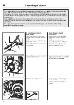
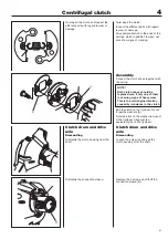
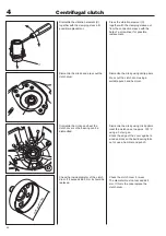
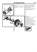
Page 36: ...34 4 Centrifugal clutch ...

Page 37: ...35 5 Angle gear 5 5 Contents Dismantling ________________________________ 36 Assembly _________________________________ 37 Drive axle _________________________________ 37 Angle gear ...

Page 38: ...ame time efficient In other words the power from the engine via the drive axle should be angled so that the cutting tool works parallel with the ground 4 Remove the circlip D 5 Remove the large circlip holding the ball bearing on the input shaft Dismantling Remove the angle gear from the shaft Remove the circlips holding the bearings on the input respective output shafts Heat the entire angle gear...

Page 39: ...een removed Assembly Clean all component parts and replace if damaged or worn Fit the bearings on respective axles This is easier if the bearings are heated to approx 110 C using a hot air gun The bearings on the input axle are sealed on one side Turn the bearings so this side faces outwards Heat the gearbox to approx 110 C and first place the output axle in position and then the input axle Make s...

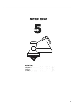
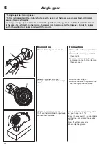
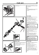
Page 40: ...38 5 Angle gear ...

Page 41: ...n valve ________________________ 41 Cleaning inspection _________________________ 41 Analysis and actions _________________________ 42 Service tips ________________________________ 46 Wear tolerances ____________________________ 46 Assembly _________________________________ 47 Cylinder and piston ...

Page 42: ...hly cleaned before being dismantled from the crankcase Dismantling Dismantle the following components to make the cylinder accessible Starter cylinder cover muffler grille muffler with heat guard plate decompression valve and spark plug Dismantle the air filter carburettor and heat guard distance piece see chapter Fuel system Then loosen the 4 bolts holding the cylinder Carefully remove the cylind...

Page 43: ...er dismantling clean the individual components 1 Scrape carbon deposits from the top of the piston 2 Scrape carbon deposits from the cylinder s combustion chamber 3 Scrape carbon deposits from the cylinder s exhaust port 4 Wash all the components 5 Inspect the different components for damage and wear Check the piston and cylinder for seizure damage and wear Also see the Analysis and actions sectio...

Page 44: ...rettor setting Change the fuel Change to a higher octane petrol Action Change to a fuel with the correct oil mixture Change to a higher octane petrol Replace damaged parts Replace leaking gaskets and shaft seals Clean the cooling fins and air intake Clean or replace the spark arrestor mesh Cause Incorrect oil mixture in the fuel Too low octane fuel Air leaks Cracked fuel hose Leaking inlet gaskets...

Page 45: ...ome loose and get trapped between the piston and the cylinder wall Typical for this type of piston damage is brown or black discoloration of the piston skirt Piston damage caused by a too high engine speed Typical damage associated with a too high engine speed includes broken piston rings broken circlip on the gudgeon pin faulty bearings or that the guide pin for the piston ring has become loose P...

Page 46: ...rn reduces the circlips tensioning power The rings can then become loose and damage the piston Bearing failure Failure of the crankshaft bearing or on the connecting rod bearing is usually caused by a too high engine speed resulting in the bearing being overloaded or overheat ing This in turn can cause the bearing rollers or ball to glide instead of rotate which can cause the roller or ball retain...

Page 47: ...ecomes loose and holes appear Air filter incorrectly fitted Air filter damaged or missing Action Fit a finer grade filter Check the filter carefully for holes and damage after cleaning Replace the filter if necessary Clean more carefully and use the right cleaning agent such as tepid soapy water Change the filter Fit the filter correctly Fit a new air filter Larger softer particles that penetrate ...

Page 48: ...e cylinder should be polished as above With deep score marks the piston and cylinder should be replaced Carefully loosen the piston rings and clean the groove well before refitting Carbon deposits in the groove impair the important heat transfer between the piston and cylinder NOTE Be careful with the lower edge of the piston ring groove If this is damaged or if carbon deposits remain the compress...

Page 49: ...er is open Place a new cylinder base gasket on the crankcase Lubricate the piston and the big end bearing with a few drops of engine oil Assemble the cylinder with the help of the piston ring compressor in the assembly set 502 50 70 01 Lubricate the seal A using engine oil and press it into the cylinder connections Pay attention to the connection for the pulse channel Check that the distance piece...

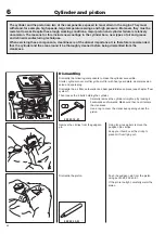
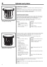
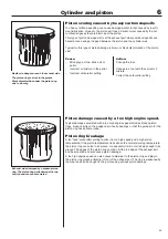
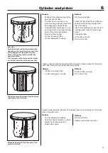
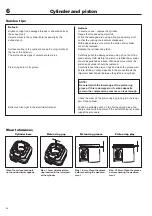
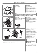
Page 50: ...48 6 Cylinder and piston ...

Page 51: ...Crankshaft and crankcase 7 7 Contents Dismantling ________________________________ 50 Inspecting the crankshaft _____________________ 52 Assembly _________________________________ 52 Crankshaft and crankcase ...

Page 52: ...r the fuel air mixture when this is sucked from the carburettor and is forced into the cylinder s combustion chamber The crankcase must be perfectly sealed so as not to affect this pump function There cannot be any leakage from the crank shaft between the crankcase halves or between the crankcase and the cylinder Always replace the sealing rings and gaskets when servicing the crankcase Dismantling...

Page 53: ...crankcase halves to 110 C using a hot air gun Dismantle the sealing rings from the crankcase halves Dismantle the sealing rings from the crankcase halves Use a suitable punch or sleeve and knock out the sealing rings with the help of a hammer Do this while the crankcase half is still warm if possible Now clean the crankcase halves and crankshaft Knock the crankcase half against a wooden block so t...

Page 54: ... the bearing track the crank shaft must be replaced Inspecting the crankshaft Inspect the large end of the connecting rod Inspecting the crankshaft The crankshaft cannot be reconditioned but must be replaced if it is worn or damaged Inspect the large end of the connecting rod If seizure marks discolouration on the sides or damaged needle holders are found the crankshaft must be replaced Check the ...

Page 55: ...ce the guide rail in position in the flush channel Place the 2 guide sleeves in the crankcase half Place a new crankcase gasket in position Fit the flywheel side s crankcase half Tighten the 4 crankcase screws crosswise Place a new crankcase gasket on the crankcase and secure if necessary with a little grease Lubricate the tapered crankshaft journal with a few drops of oil and slide the flywheel s...

Page 56: ...inder base gasket Lubricate the piston and piston rings with a few drops of oil Use the piston ring compressor and carefully slide the cylinder into position Tighten the four screws crosswise Assemble the remaining parts in the reverse order as set out for dismantling See relevant sections in the manual ...

Page 57: ..._______________________ 56 Fuel system _____________________________ 56 Centrifugal clutch _________________________ 56 Angle gear ______________________________ 57 Cylinder and piston ________________________ 57 Crankshaft and crankcase __________________ 57 Workshop equipment ______________________ 57 ...

Page 58: ...6 01 531 00 60 76 502 50 83 01 501 60 02 03 502 50 18 01 505 69 85 70 502 51 49 01 531 00 48 63 531 03 03 98 531 03 06 23 502 50 18 01 502 51 49 01 502 50 18 01 502 71 14 01 502 50 18 01 503 80 17 01 Electrical system Centrifugal clutch Starter Fuel system Fuel system ...

Page 59: ...1 03 01 502 71 14 01 503 97 64 01 531 03 06 23 502 50 18 01 505 69 85 70 101 64 23 48 502 52 42 01 503 80 17 01 502 50 70 01 502 50 18 01 502 50 70 01 Angle gear Cylinder and piston Crankshaft and crankcase Workshop equipment ...

Page 60: ......

Page 61: ......

Page 62: ...2005W23 115 00 92 26 ...

Reviews: