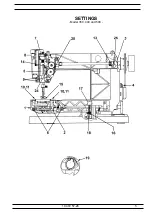
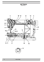
background image

600,500,400,350 

Printed in Sweden

Made in Sweden

Jan -2003

© 2003  VSM Group 

AB - 

All Rights Reserved.

SERVICE MANUAL

104 72 57-26

(Replaces  104 72 38-26) 

Summary of Contents for 500

Page 1: ...600 500 400 350 Printed in Sweden Made in Sweden Jan 2003 2003 VSM Group AB All Rights Reserved SERVICE MANUAL 104 72 57 26 Replaces 104 72 38 26 ...

Page 2: ...wer thread tension thread tension of the bobbin case 23 20 Upper thread tension 24 21 Upper thread tension only Rose Iris 25 Coarse adjustment 26 22 Upper thread tension embroidery position Only Rose Iris 27 23 Upper thread guard only for Rose Iris 28 24 Setting the thread take up spring 29 25 Disconnection when winding the lower thread 29 26 The height of the embriodery foot Only Rose Iris 30 Ser...

Page 3: ...f setting gauges and service tools is intended as an instructionabout the special service tools needed to servicing this machine 1 On several different occasions the needle is used as a setting gauge The setting ratings are adapted to needle 90 Make sure to use an undamaged needle 2 Gauge for setting the timing of the hook in relation to the needle P 16 Ref No 411 17 52 01 3 Gauge for the feed dog...

Page 4: ...ous settings which must be maintained to ensure that the machine functions satisfactorily The second section covers dismantling and mounting instructions The diagrams only give indication as to where the detail or mechanism is located in the machine For more detailed information regarding the construction etc refer to the diagrams in the spare parts list ESD ATTENTION It is of the utmost importanc...

Page 5: ...5 104 72 57 26 SETTINGS Model 350 400 and 500 ...

Page 6: ...6 104 72 57 26 SETTINGS Model Rose ...

Page 7: ... during the revolution Check 1 Rotate the hook back and forth and check the play 2 Do this check at at least 3 different spots during the revolution of the cog wheel Move the cog wheel with the hand wheel Adjustment 1 Loosen screw A in the bearing clamp 2 The play can now be adjusted by turning the eccentric bearing C NOTE The hole B in the bearing shall always be on the lower half ...

Page 8: ...centred behind the needle the tap of the worm gear should now be positioned according to fig 2 Alt Check 1 When the two taps of the worm gear are positioned according to fig 2 the tip A of the hook should point straight backwards Adjustment 1 Loosen screw B Remove the hook and set it into its correct position Note If none or only one pin is found please clean the worm gaer and look for a breaking ...

Page 9: ... 1 The needle shall be in its centre position straight stitching 2 Set the tip of hook A so is centred behind the needle the tap of the worm gear should now be positioned according to fig 3 Alt Check 1 When the two taps of the worm gear are positioned according to fig 3 the tip A of the hook should point straight backwards Adjustment 1 Loosen screw B Remove the hook and set it into its correct pos...

Page 10: ...n the two screws A of the bearing clamp 4 The belt tension can now be adjusted by turning bearing B which is eccentric NOTE The hole C should always be on the front half 4 Belt tension motor belt 1 Dismount rear cover 2 Loosen the 2 screws A and adjust the belt tension by displacing the motor NOTE Adjustment of the arm lower shaft belt affects this adjustment ...

Page 11: ...ll be parallel to the feed dog groove B and in its lifted position it shall be approx 8 mm above the stitch plate Adjustment 1 Loosen screw C and turn the presser foot until it is parallel to the feed dog groove of the stitch plate and move it until its lifting height is approx 8 mm 2 Tighten the screw ...

Page 12: ...resser foot Check 1 Sideways the hook should be symmetrically set in relation to the presser foot Adjustment 1 Loosen the 2 screws A in the feeding device 2 Move the feeding device sideways until the feed dog is right below the presser foot 3 Tighten the screws ...

Page 13: ... segment A and the calibration stop B should now be 0 2 0 3 mm Note The position on the eccentric Adjustment 1 Get into the service mode of the machine by pressing the reverse feed button and minus stitch length while the mains switch is turned on 2 Turn the hand wheel until the needle arrives at its upper turning position 600 500 400 Press key nr 3 Freesia Lisa Angelica Victoria Press key nr 2 Lo...

Page 14: ...arrives behind the needle Check the gap by pressing a small screw driver against the needle The gap should be as small as possible but max 0 15 mm Adjustment 1 If the gap is too large Turn screw A clockwise and tighten with screw B 2 If the gap is too small Loosen the screws B and A and make the gap larger Then turn screw A clockwise and tighten with screw B NOTE Always tighten with screw B Check ...

Page 15: ...d descend right into the middle of the needle hole of the stitch plate 11 The sideways setting of the stitch plate the hook cover in relation to the feed dog Check The feed dog must not touch the stitch plate at any point Adjustment Loosen the 3 screws A of the hook cover and move it so that the needle sideways descends in the middle of the stitch plate the feed dog does not touch the stitch plate...

Page 16: ...and the case holder Check at the marked positions according to fig 1 Adjustment 1 Loosen screw A 2 The gap between the hook and its cover can now be adjusted by turning the stud C right or left To the right the gap becomes larger To the left the gap becomes smaller 3 Push down the hook shaft B and tighten screw A N B This setting affects 1 The play of the hook gear 13 The timing of the hook and th...

Page 17: ...etting gauge on the needle bar so that the springloaded stud A just touches the needle bar frame and tighten the screw 3 Move the needle upwards with the handwheel until the springloaded stud A rests against its stop in the setting gauge 4 The tip of the hook should now be behind the centre line of the needle Adjustment 1 Remove the blank pointed screw B and loosen the other 2 screws in the belt w...

Page 18: ... 15 0 2 mm The check is executed with a polished needle 90 which is 29 15 mm long Order nr 412 35 29 01 Adjustment 1 Bring needle to its lower turning position 2 Loosen screw A and move the needle bar until the correct measure is obtained 3 Tighten the screw NOTE Check by means of a twin needle that the needle bar is not twisted May cause jump stitches when sewing with a twin needle ...

Page 19: ... position 2 The top of the feed dog should be 0 9 1 1 mm above the stitch plate Check with setting gauge 411 49 93 01 Adjustment 1 Bring feed dog to its highest position 2 Adjust with a screw driver the adjustment nut A until a correct feed dog height 0 9 1 1 mm is obtained ...

Page 20: ...turned on 600 500 400 Press key nr 5 Freesia Lisa Angelica Victoria Press key nr 4 the feed dog shall now stand still when the foot control is pressed 0 feeding Adjustment Loosen the screw A of the cog wheel and turn it until the feed dog comes to a stand still when the foot control is pressed Note If a basic setting has to be carried out Check that set screw B can be adjusted both ways ...

Page 21: ...d wheel until the needle arrives at its lower turning position 600 500 400 Press key nr 8 Freesia Lisa Angelica Victoria Press key nr 7 The gap between the segment A and the calibration stop B should now be 0 2 0 3 mm Adjustment 600 500 400 Press key nr 6 Freesia Lisa Angelica Victoria Press key nr 5 Loosen screw C Turn the eccentric calibration stop B until the gap between segment A and the calib...

Page 22: ...h acc to ill This adjustment may be done without dismounting the covers see ill Snap away cover C by bending in its lower edge by means of a screw driver Buttonhole balance Concerns model Rose 500 350 and 400 version 2 Can be carried out on any of the buttonholes Press and simultaneously until the text BAL flashes in the left part of the display model Rose and 500 or until the flashing of the leng...

Page 23: ... the bobbin case 2 The thread tension spring of the bobbin case shall give a resistance of 12 20 g when pulling the thread slowly Adjustment 1 Turn screw A until the correct thread tension is obtained NOTE Before any adjustment is made remove any loose pieces of thread or fluff from the thread tension discs ...

Page 24: ...thin the marked area Adjustment 1 Run the machine and turn the thread tension dial A until a correct take up is obtained 2 Loosen locking washer B 3 Remove the thread tension dial A and put it back on the shaft with its white field right in front of the index NOTE Before any adjustment is made remove any loose pieces of thread or fluff from the thread tension discs ...

Page 25: ...n press the stitch length key 3 To save press any key but not the stitch length key NOTE Before any adjustment is made remove any loose pieces of thread or fluff from the thread tension discs Fine adjustment 2 This adjustment is a complement to the electronic adjustment TT and TC The adjustment can be made in 5 steps 2 steps The maximum adjustment is 20 gram Each step is 10 gram This adjustment ca...

Page 26: ...cording to instruction below Dismounting instructions 1 Loosen the screws of the circuit board and partley remove it 2 Remove C washer C washer D and cog segment H 3 Loosen the screws of the thread tension unit and partley remove it 4 Loosen the locking washer I 5 Remove the cogwheel J Mounting instruction 1 Place the edge of the rack K right above the index mark L of the thread tension casing acc...

Page 27: ...ey simultaneously Instead of a stitch number TC is shown on the display and instead of the stitch length a setting value The value can be set between 6 and 6 the value on the display is changed gradually each time you press the key The machine will always remember the most recently set value Sew and press the or the of the stitch length key until a correct take up is obtained If you wish a harder ...

Page 28: ... the right corner of the display If it switches between 2 different positions 0 and 1 while moving the thread take up spring up or down the function is correct Dismounting To be able to dismount the upper thread guard you have to 1 Loosen the contact from the step motor of the thread tension in the circuit board 2 Loosen the screws of the circuit board and partley remove it 3 Remove C washer C was...

Page 29: ...ody with a screw driver until a correct thread take up is obtained NOTE On Rose and Iris the setting of the thread take up spring affects the function of the upper thread guard 25 Disconnection when winding the lower thread Check When winding up the lower thread onto the bobbin the machine should stop when there is a min of 1 mm between the edge of the bobbin and the thread Adjustment Turn by mean...

Page 30: ...position and the needle clamp screw C against the embroidery foot according to ill 3 The distance between the embroidery foot U and and the stitch plate D should be 1 9 0 2 mm see ill Adjustment 1 Loose the nut A 2 Turn the screw B untill the distance between the embroidery foot U and and the stitch plate B is 1 9 0 2 mm see ill 3 Tighten the nut ...

Page 31: ...02 Functions of the service program Key 1 The two symbols to the right show the code letter of the program memory of the circuit board Key 2 Display test where all symbols light up on the display Key 3 Is used for the centre position of the needle in straight stitching The step motor of the needle is now in its centre position Setting nr 7 Key 4 Is used when pre setting the step motor of the needl...

Page 32: ...used to check the movement of the embroidery unit in the feeding direction Key 28 Is used together with the adapter 412 41 12 01 to make sure that the control signals of the machine to the embroidery unit are correct Key 29 Indicates which memory card is in the machine e g 1 and which program code the memory card has e g 5 Note Not mentioned keys are not used on service or have no function Electro...

Page 33: ...rogram of the Freesia 415 use the foil keyboard 412 60 55 01 the Freesia 425 use the foil keyboard 412 60 58 01 the Lisa use the foil keyboard 412 65 60 01 the Angelica use the foil keyboard 412 6974 01 the Victoria use the foil keyboard 412 7362 01 Functions of the service program Key 0 The two symbols to the right show the code letter of the program memory of the circuit board Key 1 Display test...

Page 34: ...onic button hole balance Freesia 425 415 Angelica Victoria It is not possible to do any electronic button hole balance on the Freesia 425 415 the Angelica and the Victoria Electronic button hole balance Lisa Electronic button hole balance should NOT be carried out on a Lisa If a electronic buttonhole balance is made on a Lisa it will influence the stich leghts balance on all stiches The setting of...

Page 35: ...Croatian as colour code 82 gives Polish as colour code 90 gives Czech as colour code Upper thread tension Rose Iris To facilitate the setting of the upper thread tension there is an electronic adjustment in the normal function position Operation Switch on the main switch Then select one of the following combinations Emboidery key arrow down and thread tension key plus Is used at fine adjustment of...

Page 36: ... under the handle screw B in the rear corner of the base plate and screw C at the thread knife of the sewing head 2 Cautiously bend by means of a screwdriver the 2 recesses under the stitch plate in order to expose the hook Expose the hooks D and F and remove rear cover ...

Page 37: ...ar corner of the base plate and screw C at the thread knife of the sewing head Expose hook F and remove the rear cover Lower rear cover Lily Rose 1 Loosen screw E 2 Cautiously bend with a srewdriver in the two sockets D under the stitch plate in order to expose the hook and remove the lower rear cover ...

Page 38: ...ws B from behind and screw C in the front corner of the base plate 4 Snap off cover D by bending its lower edge by means of a screwdriver 5 Carefully bend away the front cover from the hand wheel and pull it straight out 6 Loosen the band cable of the foil keyboard from the circuit board by pulling the outer covering of the white switch outwards ...

Page 39: ...istence between the contact pins 1 3 shall be approx 13 Volt AC Lamp computer 4 5 6 7 shall be approx 28 Volt AC Step motor drive motor 2 8 shall be approx 100 0 k Ohm Foot control connected Fuses On the circuit board of the transformer there are two fuses They can be exchanged without disassemble the transformer Fuse B for 120 V machines 3 5 A 250 V for 220 V machines 6 3 A 250 V Fuse C 2 A 250 V...

Page 40: ... off its support by bending its lower end outwards and thereafter pulling it downwards 5 Loosen the cables from the circuit board according to below 1 The step motor of the needle 2 The step motor of the feeding unit 3 Lamp 4 Motor mounted from the rear red cable down 5 Transformer 6 Buttonhole counter Note 1 Contacts 1 2 and 3 can be loosened by cautiously bending away the outer covering with a t...

Page 41: ... cables from the circuit board according to below 1 The step motor of the needle 2 The step motor of the feeding unit 3 The thread guard 4 The step motor of the thread tension 5 XY connection 2 6 Microswitch 7 Buttonhole counter 8 Lamp 9 Motor mounted from the rear red cable down 10 Transformer 6 Cautiously snap the guide for the memory card C and the metal sheet of the circuit board Note 1 Contac...

Page 42: ...ce sewing head with its upper part into its guide G 3 Make sure that the presser foot lever is hooked on its lever arm 4 The screw H on the cog wheel I should now be positioned opposite cog segment J when it is centred 5 Tighten screws C and D 6 Mount the step motor of the needle Tighten screws A and B Under screw A the earth cable is mounted 7 Mount the lamp cable in the circuit board Thereafter ...

Page 43: ...ount the step motor and the screws A and B N B The earth cable C shall be mounted under the screw A 3 Mount the circuit board without squeezing the cables 4 Place the needle by means of the cog segment J sideways right into the presser foot Make sure that the screw H of the cog wheel I of the step motor is straight opposite the cog segment J Note The screw mustn t descend into the cog segment on a...

Page 44: ...rcuit board and bend it down 5 Remove C washer C washer D and the cog segment H 6 Loosen the screws G Remove the step motor Mounting 1 Position the step motor compl 2 Position the index mark M of the rack right opposite the index mark O of the step motor 3 Position the index mark P of the cog segment right opposite the index mark IM of the rack 4 Mount washer D and C washer C 5 Mount the circuit b...

Page 45: ... to the right 4 Lift the step motor compl out of the machine and remove its contact from the circuit board Mounting 1 Position the step motor compl 2 Connect the connection C between the segment shaft of the step motor and the feeding unit Note Location of the guide see Fig 1 Do not turn 180 degrees wrong 3 Tighten screws B and connect contact to the circuit board Thereafter set 16 Stitch length b...

Page 46: ...feeding eccentric straight backwards 2 Insert feeding unit 3 Tighten screws B 4 Mount feeding step motor 5 Mount hook cover presser foot holder and needle Thereafter adjust 6 The setting of the feed dog in relation to the presser foot 10 The setting of the stitch plate hook cover in relation to the needle in the feeding direction 11 The sideways setting of the stitch plate hook cover in relation t...

Page 47: ...hereafter set 2 Setting of the hook in relation to the feeding eccentric 1 Play of the hook gear 6 Setting of the feed dog in relation to the presser foot 9 Gap between the needle and the hook 13 Timing of the hook in relation to the needle 14 Needle height 10 The setting of the stitch plate hook cover in relation to the needle in the feeding direction 11 The sideways setting of the stitch plate h...

Page 48: ...er ring is pushed against the ring B and is engaged when it is pushed back Dismounting 1 Dismount front cover and rear cover 2 Loosen screw A Mounting 1 Keep the bobbin device in extended position 2 Push ring B against the hand wheel 3 Push the rubber ring C of the bobbin device against ring B 4 Tighten the screw 5 Check ...

Page 49: ... the plate and press the snaps Cover upper part Dismounting Loosen the screw A on the outside of the gable screw B on the inside of the gable and screw C on the other gable Remove the cover in the direction of the arrow from the embroidery unit Mounting Mount in reverse order NOTE Make sure that all guides D on the inside of the cover are being put correctly ...

Page 50: ...over from the embroidery unit in order not to damage the circuit board and the cables Loosen the cable from the circuit board Mounting Insert the embroidery unit into the cover Connect the cord to the circuit board Tighten the screws NOTE Check that the 3 earthings B for ESD electro static discharge are correctly positioned ...

Page 51: ...mediate gear with a spring between B and a split cog wheel with a spring between on the belt wheel C There shall be some play between the cog wheels which will be absorbed by the spring pressing apart the two cog wheel halves When mounting the play may be set by only mounting one half of the cog intermediate gear loosening the screws D and pushing the cog wheels away from each other Therafter moun...

Page 52: ...e step motor shaft a split intermediate gear with a spring between B and a split cog wheel with a spring between on the belt wheel C There shall be some play between the cog wheels that will be absorbed by the spring pressing apart the two cog wheel halves When mounting the spring between the cog wheel parts shall be mounted with its ends in the small holes and the cog wheel parts shall be bent ap...

Page 53: ...it according to the service program If ER is shown A Check the cables of the machine B Replace the circuit board of the machine 2 If OK is indicated the machine is OK and the fault is in the embroidery unit 3 Check all the cables and cable connections of the embroidery unit 4 Connect the embroidery unit and check key 27 according to the service program If there is no movement in the feeding direct...

Page 54: ... running 3 Check the cables to the upper thread guard 4 Try a new upper thread guard 5 Replace the circuit board The embroidery unit does not sew the design correctly 1 Check the movements of the embroidery unit by means of the keys 26 and 27 service program 2 Sew stitch no 9 of the cassette 1 If this stitch is not OK 3 Make sure there is no sluggish running or play of the embroidery unit 4 Check ...

Reviews: