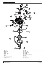
The fuel goes into the carburetor through the fuel inlet
(1). The fuel valve (2) controls the fuel flow to the
carburetor. The fuel is filtered through the fuel inlet
screen (3) before it goes into the float chamber (7).
The valve seat (4) touches the needle valve (5) at the
fuel inlet. The needle valve controls the flow of the fuel.
The needle valve moves together with the carburetor
float (6) to control the flow of fuel in the float chamber.
The lever arm (11) transmits the movement of the
carburetor float to the needle valve.
The carburetor float is in the float chamber. The
carburetor float is connected to the needle valve with the
lever arm. The carburetor float moves up if the fuel level
in the float chamber is high. The carburetor float moves
down if the fuel level in the float chamber is low.
When the fuel level decreases, the carburetor float
moves down and opens the needle valve. When the
needle valve is open, the fuel flows into the float
chamber.
When the fuel level is at the correct level, the carburetor
float moves up and the needle valve closes. This is to
prevent that too much fuel goes into the carburetor. The
float chamber keeps the fuel at a constant level.
The fuel drain screw (9) drains fuel from the float
chamber. The main nozzle (8) adjusts the fuel flow at
high speed. The needle jet (12) is the point where the
fuel goes into the venturi. The jet needle (10) is attached
to the bottom of the throttle valve (14). The jet needle
position adjusts fuel flow to the carburetor.
The idle adjustment screw (13) adjusts the idle speed.
The throttle valve adjusts the quantity of air and fuel
mixture supplied to the engine to control the engine
speed.
7.6.3 Throttle valve
In the venturi there is a throttle valve that moves up and
down to control the air flow. The jet needle is attached to
the bottom of the throttle valve. The jet needle moves up
and down with the throttle valve and adjusts the fuel
flow.
The throttle valve has 3 different positions:
•
Idle position
•
Part throttle position
•
High speed position
7.6.3.1 Idle position
22 - Repair instructions
935 - 001 -
Summary of Contents for 531RB
Page 1: ...Workshop manual 541RB 531RB English 935 001 ...
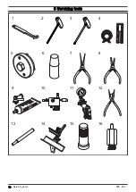
Page 10: ...5 Servicing tools 10 8 3 11 12 9 1 2 4 5 6 7 13 14 15 16 10 Servicing tools 935 001 ...
Page 61: ...935 001 Technical data 61 ...
Page 62: ...62 Technical data 935 001 ...
Page 63: ...935 001 Technical data 63 ...
Page 64: ...114 10 74 26 2019 04 18 ...


