background image

935 - 001 - 

Technical data- 61

Summary of Contents for 531RB

Page 1: ...Workshop manual 541RB 531RB English 935 001 ...

Page 2: ... 4 1 Servicing data 6 5 Servicing tools 6 Function overview 6 1 Type plate Product serial number 12 6 2 Fuel 12 7 Repair instructions 7 1 Product overview for repair instructions 13 7 2 To clean and examine the product parts 14 7 3 Starter 14 7 4 Muffler 20 7 5 Air filter 20 7 6 Carburetor 21 7 7 Centrifugal clutch 28 7 8 Ignition system 30 7 9 Cylinder and piston 35 7 10 Crankshaft and crankcase ...

Page 3: ...understand the manual 1 3 Revisions Changes to the product can cause changes to the maintenance work and spare parts Separate information is sent out for each change Read the manual together with all received information about changes to maintenance and spare parts for the product 1 4 Safety WARNING All personnel that repair or do servicing on the product must read and understand the safety instru...

Page 4: ...he product can result in permanent hearing loss 2 4 Symbols on the product WARNING This product is dangerous Injury or death can occur to the operator or bystanders if the product is not used carefully and correctly To prevent injury to the operator or bystanders read and obey all safety instructions in the operator s manual Please read the operator s manual carefully and make sure that you unders...

Page 5: ...ge and make sure that they are attached correctly For cutting attachments with a support cup tighten the nut fully For cutting attachments with a locknut tighten the locknut fully Examine the transport guard for damage and make sure that it can be at tached correctly Examine the engine the fuel tank and the fuel lines for leaks Clean the air filter Replace if it is necessary X Tighten nuts and scr...

Page 6: ...rt start starter T27 T27 T27 22 mm 12 mm 14 7 19 6 Nm 17 mm 11 17 Nm 12 18 Nm 2 9 3 9 Nm 4 9 7 8 Nm 2 9 4 4 Nm 2 9 4 4 Nm 2 9 5 0 Nm 2 9 4 4 Nm T27 6 9 9 8 Nm 2 0 3 5 Nm 7 3 8 3 Nm 10 12 Nm 4 9 7 8 Nm T27 T27 T27 T27 6 Servicing data 935 001 ...

Page 7: ...3 4 5 Nm 1 5 2 5 Nm 5 8 Nm 5 8 Nm 5 8 Nm 15 22 Nm 2 0 3 5 Nm T27 T27 T27 T27 T27 T27 19 mm 10 mm 14 mm 935 001 Servicing data 7 ...

Page 8: ...1 6 2 9 Nm 1 6 2 9 Nm 1 6 2 9 Nm 2 0 2 9 Nm 1 0 2 0 Nm 3 mm 4 mm 3 mm 8 Servicing data 935 001 ...

Page 9: ... 6 2 9 Nm 17 mm 15 20 Nm 10 mm 6 9 8 8 Nm 10 mm 6 9 8 8 Nm T27 1 6 2 9 Nm 6 9 8 8 Nm T27 T27 6 9 8 8 Nm T27 10 mm 3 0 5 0 Nm 1 5 2 9 Nm 4 mm 4 9 6 9 Nm 1 5 2 9 Nm 17 mm 15 20 Nm 935 001 Servicing data 9 ...

Page 10: ...5 Servicing tools 10 8 3 11 12 9 1 2 4 5 6 7 13 14 15 16 10 Servicing tools 935 001 ...

Page 11: ...parts in the angle gear 503 97 64 01 10 Ignition tester Spark strength check 501 97 64 01 11 Pressure tester Pressure test 531 03 06 23 12 Ignition cable pliers Repair the ignition cable 502 50 06 01 13 Pin Lock the angle gear 502 02 61 02 14 Assembly fixture Hold the product in position during maintenance 502 51 03 01 15 Bearing removal tool Remove the bearing from the crank case 505 38 17 09 16 ...

Page 12: ...o stroke oil For best results and performance use Husqvarna two stroke oil which is specially formulated for our two stroke engines If Husqvarna two stroke oil is not available you may use another two stroke oil of good quality that is intended for air cooled engines Contact your dealer when you select an oil Do not use two stroke oil intended for water cooled outboard engines also referred to as ...

Page 13: ...7 Repair instructions 7 1 Product overview for repair instructions 12 2 8 5 4 3 10 7 9 6 1 11 14 13 935 001 Repair instructions 13 ...

Page 14: ...river to decrease the resistance of the starter spring 7 3 1 To disassemble the standard starter WARNING Use protective glasses to prevent injury to the eyes if the recoil spring ejects 1 Remove the 4 screws Remove the starter 2 Pull out the starter rope approximately 30 cm 3 Put your thumb on the starter pulley 4 Put the starter rope in the groove in the starter pulley 5 Let the starter pulley ro...

Page 15: ...pulley rotate rearward until the spring tension loosens WARNING Be careful the recoil spring can cause injury to your thumb when the starter pulley rotates rearward 6 Remove the screw A A B C D E 7 Remove the starter pulley driver B and the spring C from the starter pulley D 8 Remove the starter pulley D The starter spring is in the starter pulley Only remove the plastic cover E if it is damaged W...

Page 16: ...rns counterclockwise around the starter pulley 3 Put the recoil spring in the groove of the starter housing Push down the recoil spring with your thumb on the inner side of the starter housing Move your thumb around the edge of the starter pulley and push down the recoil spring turn after turn 4 Lubricate the recoil spring and the stub axle of the starter pulley with cold resistant grease or thin ...

Page 17: ...lution more e Remove your thumb and let the starter rope wind up on the starter pulley 9 Install the starter on the product Hold the starter in position and tighten the 4 screws 10 Tilt the starter slightly forward to make sure that the starter is installed correctly on the cylinder cover and on the muffler 11 Pull the starter rope handle slowly to engage the starter pawl with the starter wheel 12...

Page 18: ... rope through the opening in the starter housing 6 Put the starter pulley D on the axle of the starter housing Make sure that the recoil spring F is in the groove G in the axle Lubricate the spring C and install it in the starter pulley Install the starter pulley driver B to the starter pulley and attach the screw A Install the plastic cover E A B C D E F G 18 Repair instructions 935 001 ...

Page 19: ...ct Hold the starter in position and tighten the 4 screws 10 Tilt the starter slightly forward to make sure that the starter is installed correctly on the cylinder cover and on the muffler 11 Pull the starter rope handle slowly to engage the starter pawl with the starter wheel 12 Do a check that the starter works 7 3 5 To replace the starter pawl assembly 1 Remove the starter Refer to To disassembl...

Page 20: ... clean and examine the muffler WARNING Risk of burn injury or fire The muffler becomes very hot during operation WARNING Risk of fire The exhaust gases are hot and can contain sparks 1 Clean the muffler with a wire brush 2 Clean the muffler cover with a moist cloth 3 Examine the muffler for wear and damage Replace the muffler if it is damaged 4 Examine the remaining parts Replace worn or damaged p...

Page 21: ...7 5 3 To apply oil to the air filter CAUTION Always use Husqvarna special air filter oil Do not use other types of oil WARNING Put on protective gloves The air filter oil can cause skin irritation 1 Put the air filter in a plastic bag 2 Put the oil in the plastic bag 3 Rub the plastic bag to supply the oil equally across the air filter 4 Push the unwanted oil out of the air filter while in the pla...

Page 22: ...o the float chamber When the fuel level is at the correct level the carburetor float moves up and the needle valve closes This is to prevent that too much fuel goes into the carburetor The float chamber keeps the fuel at a constant level The fuel drain screw 9 drains fuel from the float chamber The main nozzle 8 adjusts the fuel flow at high speed The needle jet 12 is the point where the fuel goes...

Page 23: ...or Gravity causes the fuel to go from the fuel tank to the carburetor The fuel valve B is installed between the fuel tank and the carburetor and stops the fuel The gravity fuel supply limits the product from tilted operation If the product is tilted too much the fuel does not go into the carburetor B 935 001 Repair instructions 23 ...

Page 24: ...4 26 20 12 23 16 27 1 Top cap 2 Piston valve 3 Spring 4 Needle valve 5 Hose 6 Screw 7 Float chamber housing 8 Carburetor float 9 Gasket 10 Axle 11 Lever arm 12 Needle valve 13 Fuel jet 14 Idle adjustment screw 15 Nut 16 Washer 17 Choke lever 18 Choke plate 24 Repair instructions 935 001 ...

Page 25: ...e fuel valve must be closed 1 Pull up the knob and remove the drive shaft tube 2 Disconnect the cables and throttle wire 3 Remove the air filter and air filter holder Refer to To remove and install the air filter on page 20 4 Open the clamp and remove the fuel hose from the carburetor 5 Remove the screws A and remove the carburetor B gaskets C and E and the distance piece D A B C E D 935 001 Repai...

Page 26: ... R and the fuel jet S P Q R S 11 Remove the idle adjustment screw T T U V X Y Z AA AC AB AD AE AG 12 Remove the nut U washer V choke lever X and the choke plate Y 13 Remove the 2 screws Z and remove the adapter AA 14 Remove the 2 screws AB and the washers AC 15 Remove the fuel valve AD and the washer AE 16 Assemble the carburetor in the opposite sequence Do a leak test before you install the carbu...

Page 27: ... 25 2 To adjust the fuel flow for idle speed or middle speed Move the clip of the jet needle to the correct position B C A a Move the clip to the top groove A for low fuel flow b Move the clip to the middle groove B for standard fuel flow c Move the clip to the bottom groove C for high fuel flow 3 To adjust the fuel flow for high speed Replace the main nozzle a Use a smaller main nozzle to increas...

Page 28: ...set when the product does not stop and the cutting equipment does not rotate 1 Start the engine and operate the product at half speed for 2 minutes until the engine becomes warm 2 Turn the idle adjustment screw clockwise until the cutting attachment starts to rotate 3 Turn the idle adjustment screw counterclockwise until the cutting attachment stops Note Refer to Technical data on page 60 for the ...

Page 29: ...e the 2 screws G Remove the 2 washers I Remove the centrifugal clutch H Remove the 2 washers J G I H J 7 7 2 To clean and examine the centrifugal clutch 1 Examine the spring and outer edge for wear and damage The thickness of the outer edge must be minimum 1 0 mm at the most worn point 2 Examine the parts for damage replace damaged parts 3 Clean all parts 7 7 3 To install the centrifugal clutch 1 ...

Page 30: ...of the clutch drum Replace the clutch drum if the diameter is more than 78 5 mm 7 8 Ignition system 7 8 1 Introduction The engine has an electronic ignition system fully without moving parts A defective component cannot be repaired but must be replaced by a new component If the engine does not fire the ignition module can be damaged Before you replace the ignition module do the tests that follow 7...

Page 31: ...e distance to 6 mm Note 6 mm is 6 marks on the scale 5 Pull the starter rope handle with force If the ignition module operates correctly there is a clear blue spark between the electrodes If there is no spark examine the spark plug cable 7 8 4 To examine the spark plug cable If there is no spark when you do a spark test of the ignition module you must examine the spark plug cable 1 Remove the igni...

Page 32: ...s to bend the spring CAUTION Make sure that the spring is bent 90 degrees along the cable 8 Lubricate the cap with soap and water or equivalent to make it easier to push it into position 9 Push the cable into the spark plug cap 10 Use the pliers or a screwdriver to align the spring with the hole in the spark plug cap CAUTION Be very careful to prevent damage to the spark plug cap A damaged spark p...

Page 33: ...es and throttle wire 3 Remove the 2 screws A and remove the muffler cover B Remove the screws C and D and remove the cylinder cover E A B C D E 4 Remove the spark plug cap from the spark plug 5 Disconnect the ground cable Remove the 4 screws and remove the clutch drum assembly and ignition module 935 001 Repair instructions 33 ...

Page 34: ...ston 9 Remove the 2 screws G that hold the centrifugal clutch H Remove the centrifugal clutch Remove the 2 washers I between the screws and the centrifugal clutch Remove the 2 screws J between the flywheel and the centrifugal clutch G I H J 10 Remove the nut and remove the flywheel Remove the key 11 Examine the ignition system Refer to To examine the ignition system on page 35 12 Assemble the igni...

Page 35: ... cover and the spark plug 3 Remove the cylinder cover 4 Remove the starter 5 Remove the muffler and heat shield 6 Remove the air filter cover the air filter and the air filter holder 7 Remove the carburetor the distance piece and the heat shield 8 Loosen the 4 screws Move the cylinder rearward and forward and lift it 9 Remove the cylinder base gasket Make sure that no dirt goes in the crankcase Pu...

Page 36: ...cessary 7 9 2 To clean the cylinder and piston CAUTION Clean carefully The soft aluminum parts are easily damaged Remove the carbon deposits from these parts a The top of the piston b The combustion chamber of the cylinder c The exhaust port of the cylinder Use a screwdriver to remove dirt particles from the cooling fins Clean all parts 36 Repair instructions 935 001 ...

Page 37: ...easure the piston ring groove A Replace the piston if the groove is larger than 1 6 mm A B Measure the piston ring play B Replace the piston ring if the piston ring play is larger than 0 15 mm Put the piston ring in the cylinder and measure the space with an air gap tool The space must not be more than 1 mm 7 9 4 1 To examine the piston pin Make sure that the piston pin bearing is not damaged Make...

Page 38: ...re that the piston rings do not fall into the crankcase Make sure that the piston rings are correctly attached in the grooves 4 Push in the piston pin and attach the G snap ring 5 Lubricate the piston and piston ring with 2 stroke oil 6 Put a new cylinder base gasket on the crankcase 7 Attach the support plate from the piston assembly kit Refer to Servicing tools on page 10 8 Use the clamp from th...

Page 39: ...r Remove the screws D and remove the plate C and the air filter holder E A B C D E 3 Loosen but do not remove the 2 screws that hold the carburetor Put a rubber sheet between the carburetor and the distance piece Tighten the 2 screws 4 Remove the muffler cover Loosen the 2 screws that hold the muffler Put a rubber sheet between the muffler and the cylinder start from the bottom as the illustration...

Page 40: ... Remove the rubber sheets from the muffler and the carburetor 11 Tighten the bolts to the specified torque refer to Servicing data on page 6 12 Attach the air filter holder the plate the air filter and the air filter cover 13 Install the muffler cover 7 10 Crankshaft and crankcase 7 10 1 To disassemble the crankshaft and crankcase 1 Pull up the knob and remove the drive shaft tube 2 Disconnect the...

Page 41: ... spark plug 9 Remove the ignition system and the clutch Refer to To disassemble and assemble the ignition system on page 33 10 Remove the air filter cover the air filter and the air filter holder Refer to To remove and install the air filter on page 20 11 Remove the carburetor the distance piece and the heat shield Refer to To disassemble and assemble the carburetor on page 25 12 Remove the cylind...

Page 42: ...nkcase from the frame 16 Remove the 4 screws and remove the support plate 17 Remove the screw A and remove the heat shield B Remove the 4 screws C A B C 18 Disassemble the crankcase halves 42 Repair instructions 935 001 ...

Page 43: ...seal ring 21 Use a snap ring pliers to remove the snap ring from the crankcase on the flywheel side 22 Increase the temperature of the crankcase halves to 120ºC with a hot air gun 23 Remove the bearings from the crankcase halves a On the flywheel side Carefully tap on the bearing removal tool with a rubber hammer until the bearing falls out 935 001 Repair instructions 43 ...

Page 44: ... it if it is worn or damaged 1 Examine the connecting rod Replace the crankshaft if the connecting rod is worn damaged or has discoloration 2 Examine the crankshaft bearing Make sure that there is no radial play in the connecting rod Make sure that there is axial play to sufficiently lubricate the crankshaft bearing 3 Examine the crankcase halves for cracks and damages 44 Repair instructions 935 0...

Page 45: ...hammer until the bearings are in position Make sure that the bearings are against the snap ring on the flywheel side 3 Put the seal ring in the crankcase half on the flywheel side The seal ring on the flywheel side must be 5 mm below the edge of the bearing 4 Put the crankshaft in the crankcase half on the flywheel side Lubricate the stub axle with some oil and carefully move the crankshaft into t...

Page 46: ...te easily 7 Put the small bushing on the crankcase Put an assembly sleeve on the crankshaft on the clutch side to prevent damage to the seal ring Lubricate the crankshaft with oil and install the seal ring 8 Attach the heat shield B with the screw A A B 9 Assemble the remaining parts in the opposite sequence to how they were disassembled 46 Repair instructions 935 001 ...

Page 47: ...e the fuel tank and fuel filter 1 Examine the fuel hose for damages 2 Examine the fuel tank for cracks 3 Clean the fuel tank 4 Examine the fuel filter If the fuel filter is clogged clean the filter with a brush If the fuel filter is damaged replace the fuel filter 7 11 3 Fuel tank cap The fuel tank cap cannot be repaired If the engine stops after a short period of time or if the O ring on the fuel...

Page 48: ...3 Remove the fuel hose from the carburetor 4 Remove the nut and the washers 5 Remove the product body from the harness frame 6 Remove the 6 nuts 7 Remove the plate 48 Repair instructions 935 001 ...

Page 49: ... plate B Do not remove the 4 nuts C from the rear plate B if it is not necessary 12 Assemble the harness frame in the opposite sequence 7 13 Handle and throttle trigger 7 13 1 To disassemble and assemble the handle and the throttle trigger 1 Pull up the knob and remove the drive shaft tube 2 Disconnect the cables and throttle wire 3 If the product has a hand throttle handle do these steps 935 001 ...

Page 50: ...ve the top cover b Pull the throttle trigger assembly forward Remove the throttle wire 4 If the product has a thumb throttle handle do these steps a Remove the screw b Pull out the throttle unit c Remove the throttle wire 50 Repair instructions 935 001 ...

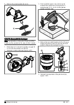
Page 51: ... 7 Remove the loop handle The models have different handles as shown in the illustrations below a Remove the 3 screws washers and nuts and remove the loop handle b Remove the screw and nut Remove the bracket and remove the loop handle from the drive shaft tube 8 Assemble the handle and the throttle trigger in the opposite sequence 7 14 Gearbox Note There are 2 different gearboxes for this product ...

Page 52: ... the support cup D A B C D 3 Remove the screws E the bracket G and the cutting attachment guard I Remove the bracket H if it is not attached to the cutting attachment guard with glue E G H I 4 Loosen but do not remove the screw J Remove the screw K Remove the gearbox L from the drive shaft tube M J K L K M 52 Repair instructions 935 001 ...

Page 53: ...g head A A 3 Remove the screws B the bracket C and the cutting attachment guard E Remove the bracket D if it is not attached to the cutting attachment guard with glue B C D E 4 Loosen but do not remove the screw H Remove the screws F and G Remove the gearbox I from the drive shaft tube J F G H I J 935 001 Repair instructions 53 ...

Page 54: ...rbox on page 53 2 Use pliers to remove the snap rings O and P O P 3 Put on protective gloves Use a hot air gun to increase the temperature of the angle gear to approximately 110 C 140 C Hit the gearbox against a wooden block 4 Remove the input shaft assembly Q from the gear housing Remove the snap ring S from the input shaft V Remove the bearings T and U U V Q T S R 5 Increase the temperature of t...

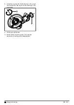
Page 55: ...mperature of the gear housing to approximately 140 C with a hot air gun 4 Put the output shaft into the gear housing L Make sure that the bearings are in their correct positions If it is necessary use a bearing press of an applicable size 5 Make sure the output shaft is attached to the gear housing 6 Install the bearings T and U on the input shaft V Install the snap ring S to the input shaft V Mak...

Page 56: ...earing on the output shaft Install the snap ring P for the bearings on the input shaft O P 9 Fill the gear with grease 10 Assemble the remaining parts in the opposite sequence to how they were disassembled 56 Repair instructions 935 001 ...

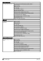
Page 57: ...or is not attached correctly The lever arm of the needle valve does not operate correctly The idle speed is too low Defective heat insulation seal The lever arm of the needle valve is damaged The lever arm of the needle valve is too high The lever arm of the needle valve does not operate correctly The needle valve is worn Object in the needle valve groove The idle speed does not become stable The ...

Page 58: ...Incorrect unsatisfactory fuel The needle valve is defective The carburetor is not attached correctly The lever arm of the needle valve is damaged The lever arm of the needle valve does not operate correctly The needle valve spring is damaged The needle valve spring is not attached correctly The needle valve is worn Object in the needle valve groove Increase and decrease speed The engine does not i...

Page 59: ...ecreased The lever arm of the needle valve is too high The lever arm of the needle valve does not operate correctly The needle valve is worn Object in the needle valve groove The engine cannot increase speed Defective heat insulation seal 935 001 Troubleshooting 59 ...

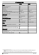
Page 60: ... 1 Carburetor Type Float piston valve Float piston valve Weight Without fuel cutting attachment and guard kg 9 0 9 0 Sound levels1 Equivalent sound pressure level at the operator s ear measured according to EN ISO 11806 and ISO 22868 dB A min max 87 87 Vibration levels2 Equivalent vibration levels ahv eq at handles measured according to EN ISO 11806 and ISO 22867 m s2 Equipped with Grass blade gri...

Page 61: ...935 001 Technical data 61 ...

Page 62: ...62 Technical data 935 001 ...

Page 63: ...935 001 Technical data 63 ...

Page 64: ...114 10 74 26 2019 04 18 ...

Reviews: