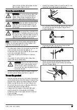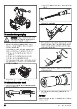
To disassemble the two-piece shaft
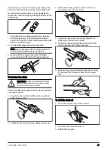
1. Turn the knob 3 turns or more to loosen the
coupling.
2. Push and hold the button (C).
3. Hold tight in the end of the shaft that the engine is
attached to.
4. Pull the attachment straight out of the coupling.
C
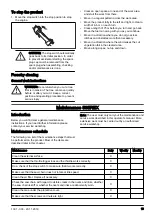
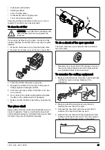
To assemble the loop handle
1. Put the loop handle onto the shaft, between the
arrows.
2. Put the spacer into the slot of the loop handle.
3. Install the nut, the knob and the screw. Do not
tighten fully.
4. Adjust the product to an applicable operation
position.
5. Tighten the knob.
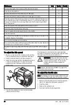
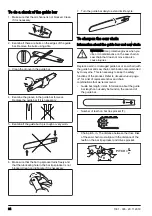
To assemble the bar and chain
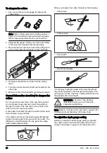
1. Unscrew the bar nut and remove the protective
cover.
2. Fit the bar over the bar bolt. Place the bar in its
rearmost position. Place the chain over the drive
sprocket and in the groove on the bar. Begin on the
top side of the bar.
3. Make sure that the edges of the cutting links are
facing forward on the top edge of the guide bar.
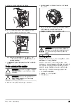
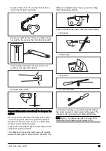
4. Fit the cover and locate the chain adjuster pin (A) in
the hole in the bar. Check that the drive links of the
chain fit correctly on the drive sprocket (B) and that
the chain is in the groove in the bar (C). Tighten the
bar nut finger-tight.
B
A
C
5. Tension the chain by turning the chain tensioning
screw clockwise using the combination spanner. The
chain should be tensioned until it does not sag from
the underside of the bar.
12
1301 - 003 - 20.11.2019
Summary of Contents for 535FBX
Page 121: ...1301 003 20 11 2019 121 ...
Page 122: ...122 1301 003 20 11 2019 ...
Page 123: ...1301 003 20 11 2019 123 ...


