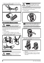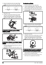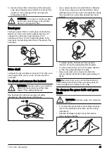
6. Make sure that the drive disc and support flange
engages correctly in the centre hole of the grass
blade.
7. Attach the nut (G).
8. Tighten the nut with the socket wrench. Hold the
shaft of the socket wrench near the blade guard.
Tighten in the opposite direction to how the cutting
attachment rotates. Tighten it to a torque of 35-50
Nm.
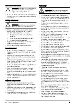
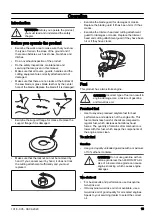
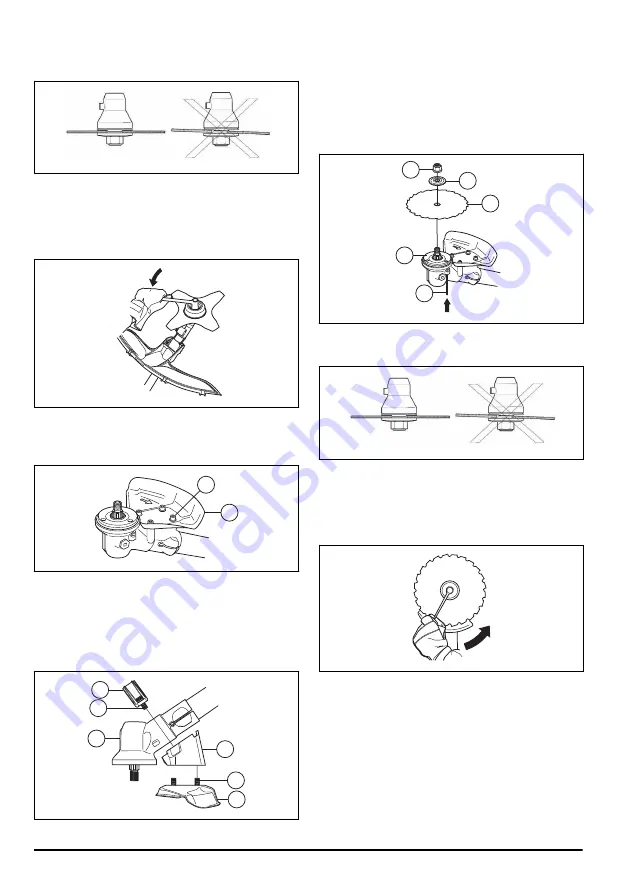
To attach the saw blade guard on 545FX,
545FXT and 545F
• Attach the saw blade guard (A) with the 4 screws (L).
A
L
To attach the saw blade guard 545FR, 545RX,
545RXT
1. Attach the holder (A) and bracket (B) with 2 bolts (C)
on the gear housing (D).
2. Attach the saw blade guard (E) with 4 bolts (F) in the
holder (A).
B
C
D
F
A
E
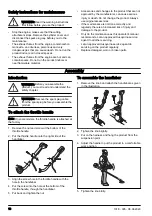
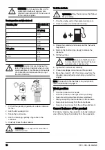
To attach the saw blade
1. Put the drive disc (A) on the output shaft.
2. Turn the output shaft to align 1 of the holes in the
drive disc with the related hole in the gear housing.
3. Put the locking pin (B) in the hole to lock the shaft.
4. Put the saw blade (C) and the support flange (D) on
the output shaft.
D
E
C
A
B
5. Make sure that the drive disc and support flange
engages correctly in the center hole of the grass
blade.
6. Attach the locknut (E).
7. Tighten the locknut with the socket wrench. Hold the
shaft of the socket wrench near the blade guard.
Tighten in the opposite direction to how the cutting
attachment rotates. Tighten it to a torque of 35-50
Nm.
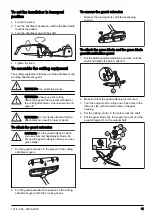
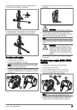
To attach the trimmer guard or combination
guard for trimmer head and plastic blades
1. Hang the trimmer guard/combination guard (A) onto
the two hooks on the plate holder (M).
2. Bend the guard around the shaft and attach it with
the bolt (L) on the opposite side of the shaft.
12
1018 - 005 - 08.06.2020
Summary of Contents for 545F
Page 105: ......
Page 107: ......
Page 108: ...A 2 7 4 0 mm 105 160 B 8 m 26 C 15 cm 5 9 1 2 3 5 6 7 9 4 8 6 15 cm B C A T55x Clic ...
Page 109: ... Clic 1 2 3 5 6 7 9 10 m 32 4 8 4 3 m 14 2 7 3 3 mm 106 13 10 cm 4 6 15 cm T45 T45x ...
Page 110: ...1018 005 08 06 2020 ...
Page 111: ...1018 005 08 06 2020 ...


