5 Handle system
5.1 Dismantling the stop switch
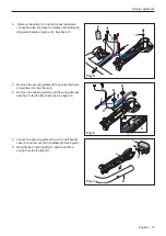
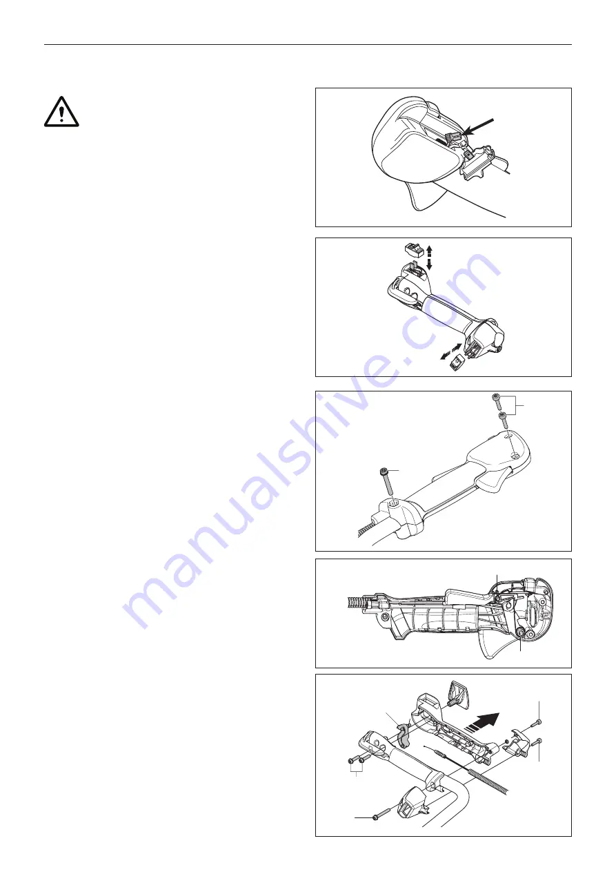
1. Carefully remove the stop switch (and heater switch,
if equipped) using a flat screwdriver or similar tool.
2.
Disconnect the cables. See figure 1a for finger
throttle and figure 1b for thumb throttle.
5.2 Cleaning and inspection
1. Clean and inspect the stop switch carefully.
2. Parts must be replaced if cracked or show signs of
other defects. Always use original spare parts.
5.3 Assembling the stop switch
1.
Connect the cables to the stop switch. See figure 1a
or figure 1b.
2. Fit the stop switch.
5.4
Dismantling the throttle (finger)
1.
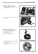
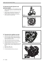
Remove the screw (A) that hold the shaft.
See figure 2.
2.
Remove the screws (B) that hold the handle
together.
3.
Note how the recoil spring (C) and the throttle lock
C
D
A
B
Safety equipment
Fig. 1a
Fig. 2
Fig. 3
Fig. 1b
Fig. 4
CAUTION: Always make sure that the stop
switch and locking mechanism is fully
functional after assembly.
A
B
C
A
A
A
(D) is mounted. See figure 3.
5.5
Dismantling the throttle (thumb)
1. Make sure that the stop switch and heater switch is
disconnected as in “5.1 Dismantling the stop switch”
2.
Remove the screws (A) and split the handle casing.
See figure 4 (Electrical wiring excluded).
3.
Disconnect the throttle wire (B) from the throttle lever
(C). See figure 4.
14 – English
Summary of Contents for 545FX AT
Page 1: ...Workshop manual English 545RXT AT 545FX AT 545FXT AT 545FX 545FXT 545RX 545RXT ...
Page 2: ......
Page 79: ...English 79 ...
Page 80: ...2018 10 04 115 88 11 26 ...


