8.6
Assembling the flywheel and
ignition module
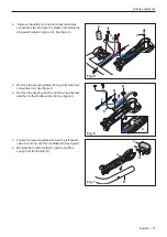
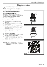
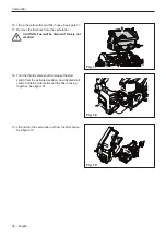
1. Inspect the key groove in the crankshaft for damage.
If it is damaged, replace the crankshaft (Reference).
See figure 9.
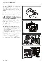
2.
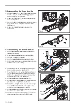
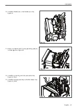
Inspect the key in the flywheel for damage. If it is
damaged,replace the flywheel. See figure 10.
3.
Attach the flywheel and tighten the nut with the
correct torque. See service data
Ignition system and heated handles
8.7 Assemble the ignition module
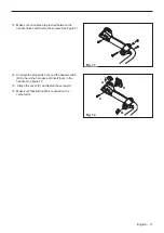
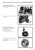
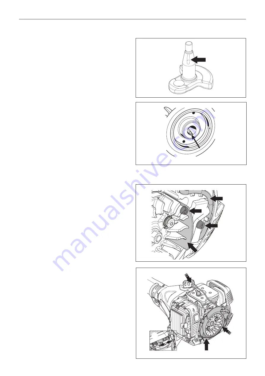
1. Position the ignition module on the crank case
2.
Position the spacer between flywheel (see fig. 11
pos. A) and ignition module and press the ignition
module against the flywheel.
3.
Tighten the bolts (B) and measure the air gap.
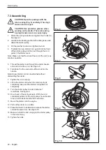
4.
Position the ignition cable in the cable channel (C).
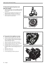
5.
Install air guide plate. See figure 12 pos. A.
6. Install AT-cables on the air guide plate and connect
the cable to the AT-module . See figure 12 pos. B
and C.
7.
Attach the air filter cover.
8. Attach the heat protector.
9.
Connect spark plug cap. See fig 12 pos. D.
Fig. 11
Fig. 12
Fig. 10
B
A
C
B
A
D
B
C
Fig. 9
28 – English
Summary of Contents for 545FX AT
Page 1: ...Workshop manual English 545RXT AT 545FX AT 545FXT AT 545FX 545FXT 545RX 545RXT ...
Page 2: ......
Page 79: ...English 79 ...
Page 80: ...2018 10 04 115 88 11 26 ...


