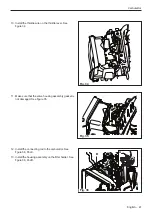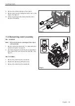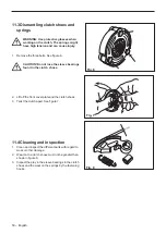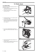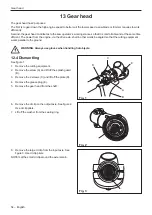
21. Tighten the frame using M5*16 screws in the bottom
of the frame (A). See figure 42. For correct torque,
see service data.
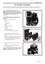
22. Tighten the frame using M5*12 screws in the upper
part of the frame (B). See figure 42. For correct
torque, see service data.
23.
Attach the cylinder cover (C) and the air filter cover
(F) and tighten the screws (E and D). See figure 42.
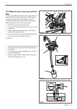
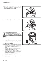
24. Make sure that the hooks in the rear part of the tank
cover is in the correct position on the tank unit when
pushing the cover into place. See figure 43.
CAUTION: Tighten screws according to
service data.
A
B
E
D
C
F
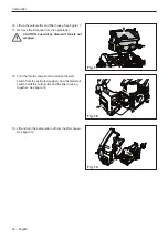
Carburettor
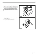
Note: Do not use any sharp tools.
Fig. 41
Fig. 42
Fig. 43
English – 43
Summary of Contents for 545FX AT
Page 1: ...Workshop manual English 545RXT AT 545FX AT 545FXT AT 545FX 545FXT 545RX 545RXT ...
Page 2: ......
Page 79: ...English 79 ...
Page 80: ...2018 10 04 115 88 11 26 ...


