background image

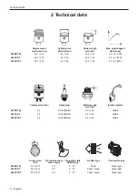
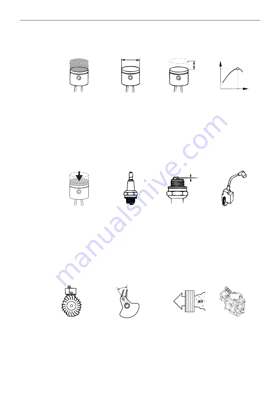
2 Technical data

Displacement  

cm3/cubic inch

Cylinder bore 

Ø mm/Ø inch

Stroke length 

mm/inch

Max. output/speed 

kW/hp/rpm

545RXT AT

45.7 / 2.79

42 / 1.65

33.0 / 1.30

2.2 / 2.7 / 9000

545FX AT

45.7 / 2.79

42 / 1.65

33.0 / 1.30

2.2 / 2.7 /9000

545FXT AT

45.7 / 2.79

42 / 1.65

33.0 / 1.30

2.2 / 2.7 9000

Compression ratio

Spark plug

Electrode gap  

mm/inch

Ignition system

545RXT AT

9.2

NGK CMR6H

0.5 / 0.02

Walbro

545FX AT

9.2

NGK CMR6H

0.5 / 0.02

Walbro

545FXT AT

9.2

NGK CMR6H

0.5 / 0.02

Walbro

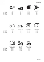
Air gap mm/

inch

Pre-ignition angle  

max output

Pre ignition Idle 

RPM Range

Air filter type

Carburettor type

545RXT AT

0.3 / 0.012

32°

2° - 27°

Paper

Diaphragm

545FX AT

0.3 / 0.012

32° 

2° - 27°

Paper / Nylon

Diaphragm

545FXT AT

0.3 / 0.012

32° 

2° - 27°

Paper / Nylon

Diaphragm

Technical data

6 – English

Summary of Contents for 545FX AT

Page 1: ...Workshop manual English 545RXT AT 545FX AT 545FXT AT 545FX 545FXT 545RX 545RXT ...

Page 2: ......

Page 3: ...emble the ignition module 28 9 Carburettor 29 9 1 Description 29 9 2 Design 29 9 3 Function 29 9 4 Removing the carburettor from engine unit 31 9 5 Dismantling 35 9 6 Assembling 38 9 7 Assembling the carburettor on the engine unit 40 9 8 After replacing the carburettor AutoTune 44 9 9 Engine adjustment 44 10 Fuel system 45 10 1 Dismantling the air filter 45 10 2 Cleaning and inspection of the air ...

Page 4: ...s are used to point out specially important parts of the workshop manual WARNING Used if there is a risk of injury or death if the instructions are not followed CAUTION Used if there is a risk of material damage if the instructions are not followed 1 4 2 Special safety instructions WARNING Before you repair or do servic ing on this product please read and under stand the following warnings Always ...

Page 5: ...s or fatal injury to the operator or others Read the operator s manual and make sure that you understand the instructions before you use this product Use protective helmet approved hearing protection and approved eye protection Always use approved protective gloves Use sturdy non slip boots Purge bulb Maximum speed of output shaft rpm Look out for thrown objects and ricochets Keep persons and anim...

Page 6: ...7 9000 Compression ratio Spark plug Electrode gap mm inch Ignition system 545RXT AT 9 2 NGK CMR6H 0 5 0 02 Walbro 545FX AT 9 2 NGK CMR6H 0 5 0 02 Walbro 545FXT AT 9 2 NGK CMR6H 0 5 0 02 Walbro Air gap mm inch Pre ignition angle max output Pre ignition Idle RPM Range Air filter type Carburettor type 545RXT AT 0 3 0 012 32 2 27 Paper Diaphragm 545FX AT 0 3 0 012 32 2 27 Paper Nylon Diaphragm 545FXT ...

Page 7: ... Bevel gear ratio Control drive disc mm inch Shaft diameter Ø mm Ø inch 545RXT AT 35 1 4 25 4 1 32 1 26 545FX AT 24 1 29 25 4 1 32 1 26 545FXT AT 24 1 29 25 4 1 32 1 26 Kg lbs GAS Drive axle diameter Ø mm Ø inch Weight kg lbs Volume fuel tank Litre US pint 545RXT AT 9 0 35 8 6 19 0 1 2 1 545FX AT 9 0 35 8 2 18 1 1 2 1 545FXT AT 9 0 35 8 4 18 4 1 2 1 Technical data Kg lbs English 7 ...

Page 8: ...Service tools 3 Service tools 3 mm 4 mm 5 mm 1 11 4 6 9 7 10 8 5 2 12 3 13 14 15 16 17 8 English ...

Page 9: ... 23 01 10 Service tool Metering lever height gauge 590 58 54 01 11 Service tool Clutch drum removal 502 52 16 02 12 Detergent Active cleaning 505 69 85 70 13 Puller Locking screw puller 502 50 65 01 14 Grease Bevel gear grease 503 97 64 01 15 Grease Drive shaft grease 503 80 17 01 16 Pressure tester Pressure testing cylinder 576 38 48 01 17 Cover plate inlet Closure of inlet 574 71 14 01 18 Cover ...

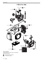
Page 10: ...Nm 4 mm 3 4 Nm 4 mm 6 7 Nm 4 mm 0 5 1 0 Nm 4 mm 1 2 Nm Max 0 5 Nm 4 mm 3 4 Nm 4 mm 2 3 Nm Key to diagrams The figures next to parts screwed on indicate the tightening torque Nm Lubricate with two stroke oil Lubricate with grease 10 English ...

Page 11: ...Service data 57 78 Ncm 135 180 Ncm 57 78 Ncm 4 mm 2 3 Nm 4 mm 7 8 Nm 4 mm 4 mm 3 4 Nm 4 mm 2 3 Nm 4 mm 7 9 Nm T27 7 9 Nm T27 7 9 Nm 4 mm 3 4 Nm English 11 ...

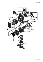
Page 12: ...ce data 4 mm 5 6 Nm 13 mm 22 25 Nm 10 mm 12 14 Nm 4 mm 9 12 Nm 4 mm 4 5 Nm 16 mm 14 16 Nm 4 mm 7 9 Nm 13 mm S N 191300901 40 45 Nm 4 mm 7 9 Nm 4 mm 3 4 Nm 13 mm S N 191300901 15 20 Nm Lorem ipsum 12 English ...

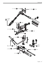
Page 13: ...Service data 19 mm 35 50 Nm 4 mm 1 5 2 5 Nm 4 mm 3 4 Nm 4 mm Max 2 5 Nm 4 mm 3 4 Nm 4 mm 1 5 2 5 Nm 4 mm 1 2 Nm 4 mm 1 2 Nm 4 mm 8 10 Nm 5 10 Nm 13 mm 4 mm 0 5 1 Nm 4 mm 4 5 Nm 1 5 2 5 Nm English 13 ...

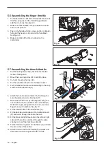
Page 14: ... the stop switch 5 4 Dismantling the throttle finger 1 Remove the screw A that hold the shaft See figure 2 2 Remove the screws B that hold the handle together 3 Note how the recoil spring C and the throttle lock C D A B Safety equipment Fig 1a Fig 2 Fig 3 Fig 1b Fig 4 CAUTION Always make sure that the stop switch and locking mechanism is fully functional after assembly A B C A A A D is mounted See...

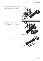
Page 15: ... D B 5 Remove the securing plates B by gently twisting a screwdriver A See figure 6 6 Remove the heating unit D and the wiring harness attached to the throttle cable C See figure 6 7 Loosen the securing plate screw on the left handle case A and remove the handlebar B See figure 7 8 Bend off the thumb throttle C and twist off the spring from the throttle D A C D B C B A English 15 ...

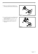
Page 16: ...nd dark blue cable leading to the stop switch with the plastic hat E D B B A C E 6 Attach the handle bar and fixate it by fastening the securing plate screw A See figure 10 7 Mount the throttle lever by inserting the spring end next to where the stop switch is to be mounted B Rotate it to apply spring tension and use you index finger to keep it in position See fig 10 8 Fit the throttle cable in th...

Page 17: ...crews See figure 11 C D A B 14 Connect the stop switch A and the heater switch B to the wiring harness and insert them in the handle See figure 12 15 Attach the cover C and fasten the screw D 16 Make sure that full throttle is reached on the carburettor Fig 11 Fig 12 English 17 ...

Page 18: ...e the locking catch has been removed The element can get damaged One heating element is placed in the throttle lock out 4 Press the locking catch from the throttle Make sure not to lose the spring A 5 Pry off the locking catch B and lift out the heating element C See figure 2 1 Remove the throttle from the handle See 5 4 Dismantling the throttle finger on page 14 2 To remove the heating element re...

Page 19: ...d in a pocket in the outside of the handle Use flat nosed pliers to pull out the heating element from the handle See figure 4 CAUTION Do not pull the cables or their connections Assemble in the opposite sequence as for dismantling CAUTION Do not pry off the heating element before the locking catch has been removed The element can get damaged Engine Heater box Right handle Left handle AT2 module Ca...

Page 20: ...er is fitted with a spark arrestor mesh clean the spark arrestor mesh with a brush and put it in place before you attach the muffler Make sure the mesh is in the correct position See fig 2 3 Remove carbon from the muffler gently with a screwdriver 6 3 Assembling Note Use the 2 screws A to thread the holes when you install the muffler to a new crankcase 1 Fit the gasket and the muffler See figure 1...

Page 21: ...s slowly 5 Remove the bolt in the centre of the starter pulley See figure 3 6 Lift the starter pulley carefully from the starter cover 7 Remove the 2 bolts that hold the spring cassette See figure 4 8 Replace the spring cassette if necessary WARNING Use protective glasses The return spring can eject and cause injury 7 2 Cleaning and inspection 1 Clean all components before assembly 2 Replace the r...

Page 22: ...through the starter handle and anchor it with a knot See figure 8 6 Fold down the free end and pull the knot into the handle Note A new starter cord can be attached without dismantling the starter 7 Tighten the return spring 8 Lift up the starter cord when the return spring is completely loose and the starter cord pulled out completely 9 Turn the starter pulley counterclockwise 7 revolutions See f...

Page 23: ...ect value with the side electrode 5 If the electrodes are worn more than 50 replace the spark plug A gap larger then 0 5 mm puts a lot of stress on the ignition module and can cause short circuiting See figure 2 6 Ground the spark plug by holding it against the cylinder See figure 3 7 Pull the starter handle sharply 8 If no spark is seen between the electrodes use a test spark plug See pos 2 in Se...

Page 24: ...ed insulation Make sure that the cables are correctly drawn and lie in the cable grooves See figure 5 Inspect the service connection for AutoTune Fig 6 and the ignition connection Fig 7 Examine the cables in the throttle See 5 6 Assembling the finger throttle on page 16 Tip Use an Ohmmeter to check if a cable is broken CAUTION The stop switch has a non locking design and must be replaced with the ...

Page 25: ...again See figure 9 3 If the spark plug still does not fire replace the ignition system See 8 2 Dismantling the ignition module on page 25 Ignition system and heated handles 8 2 Dismantling the ignition module 1 Dismantle the starter air guide plate cylinder cover muffler guard air filter cover and the spark plug frame 2 Unplug A and remove the ignition cable from the cable channel B See figure 10 ...

Page 26: ...gs by unscrewing the two screws See figure 2 4 Attach special tool See Service tools pos 7 using the same holes and screws as the drive dogs See figure 3 Ignition system and heated handles 5 Use the special tool as a counter hold an unscrew the nut See fig 11 A There after attach the special tool and screw clockwise to force off the flywheel See figure 4 Fig 1 Fig 2 Fig 3 Fig 4 B A C A B 26 Englis...

Page 27: ...ke sure that the recoil springs are in the correct position See figure 8 6 Make sure that the hooks can turn freely when the bolts are tight Ignition system and heated handles 8 5 Dismantling the generator 1 Disconnect the generator cable at the connection point See figure 5 2 Unscrew the two screws and remove the generator See figure 6 Fig 5 Fig 6 Fig 7 Fig 8 English 27 ...

Page 28: ...ignition module 1 Position the ignition module on the crank case 2 Position the spacer between flywheel see fig 11 pos A and ignition module and press the ignition module against the flywheel 3 Tighten the bolts B and measure the air gap 4 Position the ignition cable in the cable channel C 5 Install air guide plate See figure 12 pos A 6 Install AT cables on the air guide plate and connect the cabl...

Page 29: ...lves in diaphragm the fuel is transferred through a filter screen to the inlet needle See figure 1 The Autotune unit AV is attached to the metering unit B Here the correct quantity of fuel is adjusted for the actual speed and power output See figure 1 The mixing unit C houses the choke valve the throttle valve and the diffuser jets Here air is mixed with the fuel to give a fuel air mixture that ca...

Page 30: ...e valve See figure 4 pos F is partly open and the choke valve E is fully open Fuel is supplied through the diffuser jets The air throttle valve D starts to open In the full throttle mode both valves See fig 5 pos F and E are open and fuel is supplied through all diffuser jets The air throttle valve D is fully open Carburettor AV AIR FUEL MIX FUEL AIR F E AV AIR FUEL MIX FUEL AIR F D E AV AIR FUEL ...

Page 31: ...6 3 Loosen the air filter cover See figure 6 4 Remove the 4 screws See Service Data holding the filter frame See figure 7 5 Activate the start switch to make sure that it does not get stuck when you remove the filter frame See figure 8 6 Loosen the filter frame anti vibration elements from the filter house See figure 9 Carburettor Fig 6 Fig 7 Fig 8 Fig 9 English 31 ...

Page 32: ...r screws holding the air filter housing See figure 11 9 Remove the housing assy and air valve See figure 12 Pos A 10 Remove the connecting rod from the carburettor See figure 12 Pos B 11 Loosen the fuel hose on the air purge See fig 13 Pos A 12 Disconnect the connector to the stop switch See figure 13 Pos B B A A B Carburettor Fig 10 Fig 11 Fig 12 Fig 13 32 English ...

Page 33: ...m the filter house See figure 14 14 Remove the throttle wire from the throttle lever See figure 15 15 Make sure that the cable to the stop switch is loose from its holder See figure 16 Carburettor Fig 15 Fig 14 Fig 16 English 33 ...

Page 34: ...ained if tank is not emptied 18 Turn the throttle valve shaft to release the start switch from the activated position An activated start switch holds the carburettor and the filter housing together See figure 18 19 Lift and turn the carburettor out from the filter house See figure 19 Carburettor Fig 17 Fig 18 Fig 19 34 English ...

Page 35: ...cover and lift off the cover 2 Carefully remove the metering diaphragm C spiral support D and gaskets B and E 3 Inspect the diaphragm C for holes 4 Inspect the spiral support D for wear Especially inspect the contact area for the metering lever 5 Replace the diaphragm and the spiral support if required Carburettor A B C E D Fig 20 English 35 ...

Page 36: ... Remove the two 2 screws See figure 23 pos A and remove the connector holder 11 Remove the screw F that holds the cover D over the pump diaphragm C 12 Lift off the cover D the gasket B and the pump diaphragm C 13 Inspect the pump diaphragm C for damage to the valve tongues and pump surface If the valve tongues are bent or damaged the pump will not function correctly 14 Hold it up to a light and in...

Page 37: ...Carburettor 16 Use a screwdriver to remove the throttle lever A and a flat screwdriver to pry out the shaft extension B Inspect for damage and clean See fig 24 Fig 24 A B English 37 ...

Page 38: ...ing See figure 26 1 Attach the throttle lever and springs 2 Place the pump diaphragm B closest to the carburettor housing Put the gasket cover and the other components back in the opposite sequence of removal CAUTION Tension the return spring C on the shaft extension sufficiently Otherwise the pawl for the start throttle setting will not work as intended Carburettor A B Fig 26 Fig 25 38 English ...

Page 39: ...piral support metering diaphragm second gasket and metering cover on the carburettor notice the correct order in figure 26 Make sure that the aluminum surface is clean and replace gasket if it is damaged 6 Make sure that the air hole in the cover is free from obstacles and screw on the cover See figure 28 7 Connect pressure tester See Special tools to the fuel intake on the carburettor 8 Pump up t...

Page 40: ...ttor and filter house together See figure 30 4 Install the 2 screws at the bottom in the filter house that holds the carburettor See figure 31 5 Connect the fuel hose to the carburettor D See figure 32 6 Connect the ignition module to the autotune E See figure 32 7 Make sure that the AT cable is inserted in the holders F to avoid pinching A C B E D F G H Carburettor 8 Connect the fuel hose to air ...

Page 41: ... Make sure that the valve housing assembly gasket is not damaged See figure 35 12 Install the connecting rod to the carburettor See figure 36 Pos A 13 Install the housing assembly on the filter holder See figure 36 Pos B A B Carburettor Fig 34 Fig 35 Fig 36 English 41 ...

Page 42: ... full throttle while controlling that the throttle stop hits the stop See fig 39 17 Activate the start switch 18 Make sure the vibration support is not damaged and in the correct place in the frame 19 Install the frame on the engine body Start from the bottom see figure 40 Make sure that the start switch is in the correct position 20 Use a tool to press down the vibration support on the filter hol...

Page 43: ... torque see service data 23 Attach the cylinder cover C and the air filter cover F and tighten the screws E and D See figure 42 24 Make sure that the hooks in the rear part of the tank cover is in the correct position on the tank unit when pushing the cover into place See figure 43 CAUTION Tighten screws according to service data A B E D C F Carburettor Note Do not use any sharp tools Fig 41 Fig 4...

Page 44: ...Run the product for 30 seconds with WOT then release throttle Repeat this three times 5 Let the product run on idle for 5 min 9 8 After replacing the carburettor AutoTune WARNING When the engine is tested in connection with carburettor adjustment the clutch and clutch cover must be mounted together with the shaft and gear head A loose clutch can result in serious personal injury NOTE Do not remove...

Page 45: ...d filter See figure 2a Nylon weave filter only for winter use See figure 2b 10 2 Cleaning and inspection of the air filter Paper filters are cleaned using compressed air CAUTION Replace the paper filter if it is heavily soiled Clean the nylon filter in tepid soapy water or use cleaning agent See Service tools pos 13 WARNING Do not clean the filter with gasoline CAUTION Replace the nylon filter if ...

Page 46: ... bar before the tank venting valve opens 4 Lower the pressure in the fuel tank It must not drop below 5 kPa 0 05 bar before the tank venting valve opens 10 4 Cleaning the fuel cap 1 Use a screwdriver and pry off the housing A 2 Remove the nipple B using a small flat nosed pliers 3 Blow the bleeding opening in the house A clean with compressed air 4 Blow both sintered filters clean C with compresse...

Page 47: ...fuel hose A from the connection on the carburettor 3 Clamp together the spring clip and pull off the fuel hose B from the fuel pump 4 Remove the screws C and lift off the fuel pump with the suction hose and fuel filter attached See figure 5 5 Use a small screwdriver and pry the fuel hose D off of the fuel pump E to replace any damaged parts See figure 6 6 The fuel filter F must be replaced with a ...

Page 48: ...This prevents abnormal load changes on the crankshaft The engagement speed is carefully tested so that the engine can idle without the drive shaft of the cutting equipment rotating 11 1 Dismantling The clutch is located between the fuel tank and the engine To access the clutch move the tank and the handle holder forward on the shaft See figure 1 1 Empty fuel tank 2 Remove the handlebar with the wi...

Page 49: ... Note If the clutch hub is undamaged this step is not necessary 1 Remove cylinder according to 14 1 Dismantling the cylinder and piston on page 57 2 Use crank stop service tool to fix the crank shaft A then unscrew the nut to remove the clutch B See figure 5 S N 191300901 1 Remove the clutch from the crankshaft 2 Replace the spark plug with piston stop 3 Remove the clutch from the crankshaft Centr...

Page 50: ...e clutch shoes 3 Twist the clutch apart See figure 7 11 4 Cleaning and inspection 1 Clean and inspect the different parts with regard to wear or other damage 2 Wear on the clutch shoes must not be greater than shown in figure 8 3 Inspect the play in the sleeve bearings in the clutch shoes and the wear on the springs by the fastening hooks CAUTION Do not lose the sleeve bearings found in the clutch...

Page 51: ...far as possible and hook the springs to the adjacent clutch shoe from above as shown in figure 10 and 11 Use a small screwdriver or flat nosed pliers CAUTION Make sure that the spring eye is pressed into the correct position 4 Remove the screws and put the cover plates in position 5 Tighten the bolts Centrifugal clutch 11 6 Assembling clutch assembly 1 Use the crank stop service tool to fix the cr...

Page 52: ... shaft 4 The clutch drum is tightly screwed to the drive axle Hold the drive axle in a vice and remove the clutch drum using the special tool See service tools pos 12 See figure 2 5 Remove the circlip that holds the ball bearing in place in the clutch housing See figure 3 Use circlip pliers 6 Heat the clutch housing to approximately 110 C using a hot air gun 7 Knock the clutch housing against a wo...

Page 53: ...he circlip See figure 6 3 Slide the clutch drum into the ball bearing 4 Attach the drive axle tightly to the clutch drum See figure 7 5 Lubricate the drive axle with grease and slide it on the shaft 6 Clean the surfaces using a degreasing agent See Service tools pos 13 CAUTION There should be no signs of grease in the clamping joint for the shaft and clutch cover 7 Attach the clutch cover on the s...

Page 54: ...llel to the ground WARNING Always use gloves when handling hot objects 12 4 Dismantling See figure 1 1 Remove the cutting equipment 2 Remove the screw A and lift off the splash guard B 3 Remove the 2 screws C and lift off the plate D 4 Remove the grease plug E 5 Remove the gear head from the shaft 6 Remove the circlip on the output axle See figure 2 Use circlip pliers 7 Lift off the washer from th...

Page 55: ...10 Knock the gearbox against a wooden block so that the input axle and bearing fall out See figure 4 NOTE The input axle with pinion must be dismantled first 11 Remove the output axle and bearings while the gearbox is still warm 12 Use puller See Service tools pos 14 Gear head Fig 4 Fig 5 English 55 ...

Page 56: ...he axles and make sure that they rotate easily without a tendency for the cogwheels to seize Fill the gearbox with special grease See Service tools pos 15 Wipe any excess grease from the joint between the shaft and the gear head before the gear is fitted to prevent it from turning around the shaft 7 Pry away the plastic sleeve A and the O ring B on the shaft using a knife See figure 7 8 When fitti...

Page 57: ...t protector Muffler Air filter cover and frame Spark plug Flywheel Valve housing assembly Carburettor with air filter and filter holder 1 Remove throttle wire See figure 1 pos A 2 Remove screw C and remove grommet B See figure 1 3 Disconnect any cables preventing the inlet pipe F and insulation wall E from being removed 4 Loosen the screws D and remove inlet pipe F and insulation wall E See figure...

Page 58: ... piston the combustion chamber of the cylinder and the exhaust and transfer ports port of the cylinder Clean all the components Examine the different components for damage and wear Inspect the piston and cylinder for seizure damage and wear Also see 14 5 Analysis and actions on page 61 Inspect the piston ring for wear and damage Also see the Analysis and actions section Inspect the gudgeon pin If ...

Page 59: ...een the muffler E and the cylinder leaving out the heat shield and gasket C Attach the muffler and tighten the screws F See fig 2 D C F E 3 Screw the pressure testing plug G in the sparkplug hole and tighten with a block key See fig 3 4 Connect the Pressure testing tool H to the air nozzle and use your thumb to hold the cover plug in place I See figure 4 5 Apply a pressure of 80 kPa and wait 30 se...

Page 60: ...t is correctly fitted into the groove Cylinder and piston 5 Mount the piston holder D to fix the piston in place See figure 6 See Service tools pos 5 6 Place a new cylinder base gasket A on the cylinder See figure 6 7 Insert the screws B in the holes at the base of the cylinder See figure 6 8 Lubricate the piston with a few drops of engine oil and fit the cylinder using a suitable piston ring comp...

Page 61: ...e damage and take the actions required to prevent the same thing happening again 14 5 1 Insufficient lubrication The piston has small to medium size score marks usually in front of the exhaust port In extreme cases heat development can be so great that material from the piston smears along the piston skirt and even in the cylinder bore Generally the piston ring is undamaged and moves freely in the...

Page 62: ...inder Blocked air intake on the starter Blocked spark arrestor mesh in the muffler Clean or replace the spark arrestor mesh The piston ring starts to stick or is completely stuck in its groove and has therefore not been able to seal against the cylinder wall which has resulted in further intensive temperature increases in the piston Seizure scores along the entire piston skirt on the inlet and exh...

Page 63: ...emperature If the piston temperature rises above the normal working temperature the piston ring can seize in its groove consequently it will not sit deep enough in its groove The edges of the piston ring can then hit the top edge of the exhaust port and be smashed and also cause piston damage A too high engine speed can also cause rapid wear to the piston ring and play in the piston ring groove pr...

Page 64: ... pin vibrated loose A too high engine speed can cause the ends of the piston ring to hammer against the guide pin when the piston ring moves in its groove The intensive hammering can drive out the pin through the top of the piston causing serious damage also to the cylinder Cylinder and piston 64 English ...

Page 65: ...e and damage the piston 14 5 7 Bearing failure Failure of the crankshaft bearing or on the connecting rod bearing is usually caused by a too high engine speed resulting in the bearing being overloaded or overheating This in turn can cause the bearing rollers or ball to glide instead of rotate which can cause the roller or ball retainer to break The broken debris can be trapped between the piston a...

Page 66: ...The piston ring sits firmly in the groove Piston material has been worn away The lower part of the piston skirt is thinner on the inlet side than on the exhaust side Cause Action Faulty air filter Small dust particles pass through the filter Fit a finer grade filter The filter is worn out due to too much cleaning whereby small holes have appeared in the material Inspect the filter carefully for ho...

Page 67: ...ion Air filter incorrectly fitted Fit the air filter correctly Air filter damaged or missing Fit a new air filter The piston scored and worn from the piston ring down on the inlet side Larger softer particles that penetrate into the engine cause damage to the piston skirt under the piston ring as the illustration shows Larger harder particles that enter the engine cause serious damage to the under...

Page 68: ...linder should be polished as above Piston ring burnt in its groove With deep score marks the piston and cylinder should be replaced Carefully loosen the piston rings and clean the groove well before refitting Carbon deposits in the groove impair the important heat transfer between the piston and cylinder Bolts much too tight in the aluminium material 14 5 10 Wear tolerances When the surface coatin...

Page 69: ...avenging pump for the fuel air mixture when this is sucked from the carburettor and is forced into the combustion chamber of the cylinder The crankcase must be perfectly sealed so as not to affect this pump function There cannot be any leakage from the crankshaft between the crankcase halves or between the crankcase and the cylinder CAUTION Always replace the sealing rings and gaskets when servici...

Page 70: ...e crankshaft has a sliding fit in the bearing seatings 5 Remove any gasket residue from the cylinder base plane and from the contact face of the crankcase 6 Pry out the radial seals 7 Heat the crankcase halves to approx 150 C using a hot air gun 8 Place crank case on a plane surface and press the bearing out of the crank case Crankshaft and crankcase Fig 2 Fig 3 70 English ...

Page 71: ...See figure 4 5 Inspect the crank bearing Make sure that the connecting rod does not have any radial play up and down but that is has axial play See figure 6 6 Inspect the bearing and sealing for wear or damage and replace if needed See figure 7 3 Inspect the small end of the connecting rod See figure 5 4 If seizure marks or discolouration are found in the bearing track the crankshaft must be repla...

Page 72: ...kshaft to the clutch side of the crankcase half 4 Put the crankcase gasket in place and make sure that both guide pins are in position See figure 9 5 Slide the crankcase half of the flywheel side in place over the crankshaft 6 Tighten the 5 crankcase screws crosswise 1 5 See figure 10 7 Make sure that the crank shaft can rotate easily after it has been rotated several turns Also ensure that it has...

Page 73: ...rank case with mandrel See Service tools pos 22 13 Fit the piston and cylinder and the remaining parts in the opposite sequence as set out for dismantling See the respective sections for detailed information if necessary Crankshaft and crankcase CAUTION Assembly tools must be used when assembling sealing rings Make sure the tool is not damaged in any way Do not use a faulty tool Fig 12 Fig 13 Engl...

Page 74: ...Defect starter housing Check air gap between fly wheel and ignition module Change part or com plete starter if needed Check main bearings Check cylinder and piston Change part if needed Change part if needed Change part if needed Piston ring is stuck Perform Cleaning and in spection of starter housing see separate instr Check the key on flywheel and make sure that the flywheel is tightened with th...

Page 75: ...ic see Igni tion System Diagnostic instr 1 Check fuel filter 2 Check fuel houses for leakage by pressure test 3 Check if impulse hose is blocked or leaks 4 Check carburettor for leakage by pressure test see separate instr 5 Check fuel filter in the carburettor Does the engine start Does the engine start No No If product has an decompression valve check that the deco valve deactivate correct Check ...

Page 76: ...eck cylinder base 4 Check intake system 5 Check cylinder 6 Check gaskets on crankshaft 7 Check crank case Carburettor 1 Check leakage by pressure test positive pressure on fuel inlet and negative pressure on purge outlet 2 Check throttle shaft and valve function 3 Check filter screen for dirt 4 Check metering lever for wear and height Product OK Product OK Clean the engine cylinder fins fly wheel ...

Page 77: ...igni tion module Remove spark tester Run unit Does engine start and run properly End Test Inspect flywheel key and key way for sheared key Is flywheel key way damaged Problem is not in igni tion system Perform cylinder compression test Verify fuel system Replace damaged components Perform visual inspection of unit Inspect spark plug wire boot connections Repair replace any problem items NO NO YES ...

Page 78: ...rks on the corresponding scale 4 Pull firmly in the starter handle 5 A clear blue spark will be visible between the electrodes if the ignition works properly The ignition system must be capable of producing a strong spark or the engine will have performance problems particularly under load No spark or weak spark requires further diagnostics refer to ignition System Diagnostic Flow Chart 16 3 Spark...

Page 79: ...English 79 ...

Page 80: ...2018 10 04 115 88 11 26 ...

Reviews: