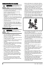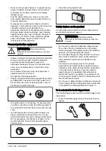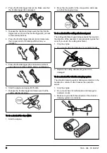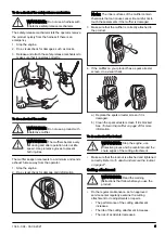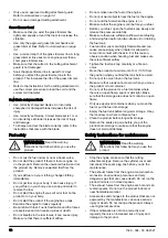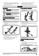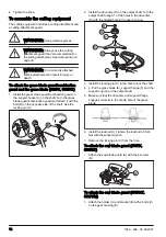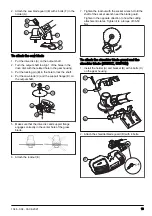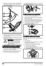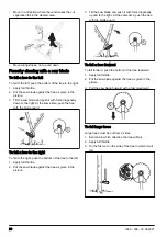
3. Install the drive disc (E). Turn the output shaft until 1
of the holes in the drive disc aligns with the related
hole in the gear housing.
I
H
G
E
F
4. Install the locking pin (F) in the hole to lock the shaft.
5. Install the shredder blade (G) and support flange (H)
on the output shaft.
6. Attach the locknut (I) with the socket wrench. Tighten
the locknut to 35-50 Nm.
WARNING:
If the locknut is not
tightened correctly, it can cause the
shredder blade to come off. This can
cause serious injury or death to the
operator or others.
To attach the trimmer guard or combination
guard for trimmer head and plastic blades
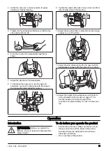
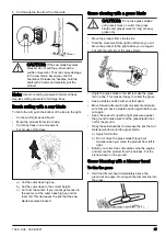
1. Hang the trimmer guard/combination guard (A) onto
the two hooks on the plate holder (M).
2. Bend the guard around the shaft and attach it with
the bolt (L) on the opposite side of the shaft.
3. Put the locking pin (C) in the groove on the bolt head
and tighten the bolt fully.
L
A
M
C
To attach a trimmer head or plastic blade
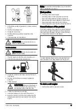
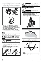
1. Put the drive disc (B) on the output shaft.
2. Align the metal cup (P) with the center of the blade
guide on the drive disc.
3. Turn the output shaft to align one of the holes in the
drive disc with the related hole in the gear housing.
4. Put the locking pin (C) in the hole to lock the shaft.
5. Turn the trimmer head/plastic blades (H)
counterclockwise to attach.
B
H
P
C
To adjust the Balance XT harness
for an overview of
the harness.
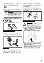
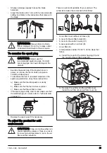
1. Stop the engine.
2. Push the safety-release mechanism down to release
the product from the harness.
3. To adjust the harness to the operator's height:
a) Push the spring loaded lock.
b) Turn the shoulder strap harness.
c) Move the shoulder strap harness to an applicable
hole on the back plate.
14
1346 - 004 - 03.06.2021
Summary of Contents for 555FRM
Page 111: ...1346 004 03 06 2021 111 ...


