background image

Summary of Contents for 917.27909

Page 1: ...Husqvarna 02148 91 7 279090 Owner s Manual ...

Page 2: ... off blades set parking brake stop engine and remove keys before dismounting Disengage blades when not mowing Shut off engine and wait for all parts to come to a complete stop before cleaning the machine removing the grass catcher or unclogging the discharge guard Operate machine only in daylight or good artificial light Do not operate the machine while under the influence of alcohol or drugs Watc...

Page 3: ...nt with a portable container rather than from a gasoline dispenser nozzle Keep the nozzle in contact with the rim of the fuel tank or container opening atall times until fueling is complete Do not use a nozzle lock open device If fuel is spilled on clothing change clothing immedi ately Never overfill fuel tank Replace gas cap and tighten securely GENERAL SERVICE Never operate machine in a closed a...

Page 4: ...e instructions will enable you to assemble and maintain your tractor properly Always observe the SAFETY RULES CUSTOMER RESPONSIBILITIES Read and observe the safety rules Follow a regular schedule in maintaining caring for and using your tractor Follow the instructions under Maintenance and Stor age sections of this owner s manual WARNING This tractor is equipped with an internal com bustion engine...

Page 5: ...at 1 Washer 17 32 x 1 3 16 x 12 Gauge 1 Knob Mower 2 Flanged Pins 2 Retainer Springs double loop J Q 4 Adjusting Bars Gauge Wheels 4 Wheels 4 Washers 3 8 x 3 4 x 14 Ga 4 Clevis Pins 4 Retainer Springs double loop 4 Locknuts 3 8 16 4 Shoulder Bolt 1 Oil Drain Tube For Future Use Keys Slope Sheet 2 Keys ...

Page 6: ...tons and remove BEFORE REMOVING TRACTOR FROM SKID ATTACH STEERING WHEEL See Fig 1 Remove Iocknut and large flat washer from steering shaft Position front wheels of the tractor so they are pointing straight forward Slide the steering sleeve over the steering shaft Position steering wheel so cross bars are horizontal left to right and slide onto steering wheel adapter Secure steering wheel to steeri...

Page 7: ...ols _ WARNING Before starting read understand and follow all instructions in the Operation section of this manual Be sure tractor is in a well ventilated area Be sure the area in front of tractor is clear of other people and objects Be sure all the above assembly steps have been com pleted Check engine oil level and fill fuel tank with gasoline Sit on seat in operating position depress clutch brak...

Page 8: ... notch is in line with the hole in pin Secure pin with double loop retainer spring between the plate and mower bracket If necessary move mower side to side to give space between plate and mower bracket Go to right hand side of mower and insert pin and retainer spring in the same manner CONNECT REAR PINS Connect right hand side first Pull out and hold the spring loaded pin align hole in suspension ...

Page 9: ...LITY PRODUCT PLEASE REVIEW THE FOLLOWING CHECKLIST All assembly instructions have been completed No remaining loose parts in carton Battery is properly prepared and charged Minimum 1 hour at 6 amps Seat is adjusted comfortably and tightened securely All tires are properly inflated For shipping purposes the tires were overinflated at the factory Be sure mower deck is properly leveled side to side f...

Page 10: ...uctions could result in serious injury or death The safety alert symbol is used to identify safety inform ation about hazards which can result in death serious injury and or property damage _I_JIIllJ l DANGER indicates a hazard which if not avoided will result in death or serious injury WARNING indicates a hazard which if not avoided could result in death or serious injury CAUTION indicates a haza...

Page 11: ...er attachments mounted to your tractor CHOKE CONTROL Used when starting a cold engine CLUTCH BRAKE PEDAL Used for declutching and brak ing the tractor and starting the engine GEARSHIFT LEVER Selects the speed and direction of tractor HEIGHTADJUSTMENT KNOB Used to adjust the mower height IGNITION SWITCH Used to start and stop the engine 11 LIFT LEVER Used to raise and lower mower deck or other atta...

Page 12: ...conditions when tractor is standing idle with the engine running hot engine exhaust gases may cause browning of grass To eliminate this possibility al ways stop engine when stopping tractor on grass areas i_ CAUTION Always stop tractor com pletely as described above before leaving the operator s position to empty grass catcher etc TO USE THROTTLE CONTROL See Fig 8 Always operate engine at full thr...

Page 13: ... hills Select desired height of cut Lower mower with attachment lift control Start mower blades by engaging attachment clutch control TO STOP MOWER BLADES disengage attachment clutch control CAUTION Do not operate the mower without either the entire grass catcher on mowers so equipped orthe deflector shield in place LIFT LEVER HIGHEST POSIITON j LOWEST POSITION ATTACHEMNT CLUTCH SWITCH PULL OUTTO ...

Page 14: ...l see the Maintenance section in this manual ADD GASOLINE Fill fuel tank to bottom of filler neck Do not overfill Use fresh clean regular unleaded gasoline with a minimum of 87 octane Use of leaded gasoline will increase carbon and lead oxide deposits and reduce valve life Do not mix oil with gasoline Purchase fuel in quantities that can be used within 30 days to assure fuel freshness I _ CAUTION ...

Page 15: ...RETOR in the Service and Adjustments section of this manual MOWING TIPS Tire chains cannot be used when the mower housing is attached to tractor Mower should be properly leveled for best mowing per formance See TO LEVEL MOWER HOUSING in the Service and Adjustments section of this manual The left hand side of mower should be used for trim ming Drive so that clippings are discharged onto the area th...

Page 16: ...eceive full value from the warranty operator must maintain tractor as instructed in this manual Some adjustments will need to be made periodically to properly maintain your tractor At least once a season check to see if you should make any of the adjustments described in the Service and Adjustments section of this manual At least once a year you should replace the spark plug clean or replace air f...

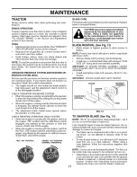
Page 17: ...ing with the ignition switch in the ROS ON position and the attachment clutch en gaged any attempt by the operator to shift into reverse should NOT shut off the engine ROS ON POSITION ENGINE ON POSITION NORMAL OPERATING BLADE CARE For best results mower blades must be kept sharp Replace bent or damaged blades CAUTION Use only a replacement blade approved by the manufacturer of your tractor Using a...

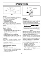
Page 18: ...oving hub bolts Remove filler plug from transaxle Oil level must be even with plug threads If necessary fill with SAE 30 motor oil API SG SL Replace filler plug Reassemble wheel to hub O TRANSAXLE CO _ 7 FILLER PLUG FIG 14 ENGINE LUBRICATION Only use high quality detergent oil rated with API service classification SG SL Select the oil s SAE viscosity grade according to your expected operating temp...

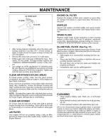
Page 19: ...fibers AIR FILTER Your engine will not run properly using a dirty air filter Service air cleaner more often under dusty conditions See Engine Manual ENGINE OIL FILTER Replace the engine oil filter every season or every other oil change if the tractor is used more than 100 hours in one year MUFFLER Inspect and replace corroded muffler and spark arrester if equipped as it could create a fire hazard ...

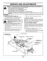
Page 20: ...move the four retainer springs and two flanged pins from front plate assembly and remove plate Raise attachment lift lever to its highest position Turn tractor steering wheel to the left as far as it will go Slide mower out from under right side of tractor TO INSTALL MOWER Follow procedure described in INSTALL MOWER AND DRIVE BELT in the Assembly section of this manual NOTE You will need to reatta...

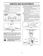
Page 21: ...hendistance B isl 8 tol 2 loweratfrontthanrear tighten nut D against trunnion on both front links To raise front of blade loosen nut D from trunnion on both front links Tighten nut C on both front links an equal number of turns The two front links must remain equal in length Whendistance B is 1 8 to 1 2 lower at frontthan rear tighten nut D against trunnion on both front links Recheck side to side...

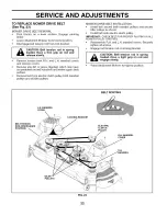
Page 22: ...ce Remove belt from electric clutch pulley both mandrel pulleys and all idler pulleys MOWER DRIVE BELT INSTALLATION Install belt around both mandrel pulleys and around idler pulleys as shown Install belt onto electric clutch pulley IMPORTANT CHECK BELT FOR PROPER ROUTINGIN ALL MOWER PULLEYGROOVES Reassemble R H and L H mandrel covers Securely tighten all screws Engage belt tension rod on locking b...

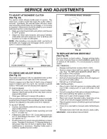
Page 23: ...RAKE Depress clutch brake pedal all the way down and en gage parking brake Measure distance between brake operating arm and nut A on brake rod If distance is other than 1 3 4 loosen jam nut and turn nut A until distance becomes 1 3 4 Retighten jam nut against nut A Road test tractor for proper stopping distance as stated above Readjust if necessary If stopping distance is still greater than five 5...

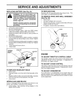
Page 24: ...curely Remove five 5 hub bolts to allow wheel removal Repair tire and reassemble Replace and tighten hub bolts securely NOTE To seal tire punctures and prevent flat tires due to slow leaks tire sealant may be purchased from your local parts dealer Tire sealant also prevents tire dry rot and corrosion 24 WASHERS RETAINING RING AXLE COVER Q FIG 27 TO START ENGINE WITH A WEAK BATTERY See Fig 28 WARNI...

Page 25: ...RD FIG 29 BLACK CABLE TO REPLACE HEADLIGHT BULB Raise hood Pull bulb holder out of the hole in the backside of the grill Replace bulb in holder and push bulb holder securely back into the hole in the backside of the grill Close hood INTERLOCKS AND RELAYS Loose or damaged wiring may cause your tractor to run poorly stop running or prevent it from starting Check wiring See electrical wiring diagram ...

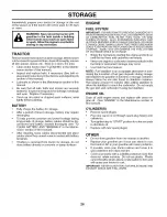
Page 26: ...ESSENTIALFUELSYSTEMPARTSSUCH AS CARBURETOR FUEL FILTER FUEL HOSE OR TANK DURING STORAGE ALSO EXPERIENCEINDICATESTHAT ALCOHOLBLENDEDFUELS CALLED GASOHOL OR USING ETHANOLOR METHANOL CANATTRACTMOISTUREWHICH LEADSTOSEPARATION ANDFORMATION OFACIDSDURING STORAGE ACIDIC GAS CAN DAMAGETHE FUEL SYSTEM OF AN ENGINEWHILE IN STORAGE Empty the fuel tank by starting the engine and let it run until the fuel line...

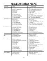
Page 27: ...lean replace air filter 2 Replace spark plug 3 Recharge or replace battery 4 Replace fuel filter 5 Empty fuel tank and refill tank with fresh clean gasoline 6 Check all wiring 7 See To Adjust Carburetor in Service Adjustments section 8 Contact an authorized service center department 1 Depress brake pedal 2 Disengage attachment clutch 3 Recharge or replace battery 4 Replace fuse 5 Clean battery ter...

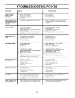
Page 28: ...n bent or loose blade 3 Replace idler pulley 4 Replace blade mandrel Buildup of grass leaves and trash under mower Mower drive belt worn Blades improperly installed Improper blades used Clogged mower deck vent holes from buildup of grass leaves and trash around mandrels 1 Place throttle control in FAST position 2 Shift to slower speed 3 Allow grass to dry before mowing 4 Level mower deck 5 Check t...

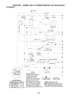
Page 29: ...00 RPM RED IF SO EQUIPPED _ _ I _ _I REGULATOR I 0 I _J_ _ _ L ALTERNATOR 1 IGNITION SWITCH POSITION CIRCUIT MAKE OFF M G A1 _UN OVERRIDt B A1 RUN B A1 L A2 START 3 S A1 02832 NOTE YOUR TRACTOR IS EQUIPPED WITH A SPECIAL ALTERNATOR SYSTEM THE LIGHTS ARE NOT CONNECTED TO THE BATTERY BUT HAVE THEIR OWN ELECTRICAL SOURCE BECAUSE OF THIS THE BRIGHTNESS OF THE LIGHTS WILL CHANGE WITH ENGINE SPEED AT ID...

Page 30: ...REPAIR PARTS TRACTOR MODEL NO 917 279090 PRODUCT NO 960 25 00 02 ELECTRICAL 12 f t i i9_ I I I I 25 34 40 33 4 5 96 16 2 i 30 ...

Page 31: ...2 Bulb Light 24 532185464 Cable Starter 25 532146149 Cable Battery 26 532108824 Fuse 27 873510400 Nut Keps Hex 1 4 20 28 532170697 Cable Ground 29 532192749 Switch Plunger 30 532193350 Switch Ign 33 532140401 Key 34 532110712 Switch Light Reset 40 532193394 Harness Ign 41 817720408 Screw Thd Cut 1 4 20 x 1 2 42 532131563 Cover Terminal Red 43 532178861 Solenoid 45 532122822 Ammeter 50 532174651 Sw...

Page 32: ...MODEL NO 917 279090 PRODUCT NO 960 25 00 02 CHASSIS AND ENCLOSURES 14 15 i_ 25 161 158 37 162 138 58 17__ 144 _130 43 34 28 17 21 2 chassis stealth II lO vgt 170 8s 4 86 17 174 _ 39 148 _156 130 18 130 84 17 17 63 17 _66 32 ...

Page 33: ...ine Chassis 158 817670608 35 819111116 Washer 11 32x11 16x16Ga 161 532181787 36 817060512 Screw 5 16 18 x 3 4 162 532142432 37 532194868 Fender 165 532183554 39 532175278 Bracket Axle Front 169 532188598 43 532136939 Bracket Spnsn Front Lh 170 532194667 44 532136940 Bracket Spnsn Front Rh 171 532184672 45 532187270 Bracket Chassis 172 817120614 50 532175476 Bracket Chassis Front 173 874780512 58 5...

Page 34: ...REPAIR PARTS TRACTOR MODEL NO 917 279090 PRODUCT NO 960 25 00 02 GROUND DRIVE 40 41 30 51 28 17 _ 37 38 50 11 48 7 69 156 24 22 15 57 47 157 155 62 drive 9 vgt 62 34 ...

Page 35: ...earing Idler 17 532126909 Spring 56 532137153 V Belt 18 532137104 Lever Brake 57 532141756 Bracket Shift Rod Hi Lo 19 532136926 Cam Brake Disc 59 532122253 Shift Rod Hi Lo 21 823260412 Screw Flat Head 1 4 28 x 3 4 60 532122268 Spring Clip Connecting Link 22 532194121 Gearshift Lever Assembly 61 532184787 Pulley Transaxle 23 532106932 Knob 62 810040700 Washer Lock 7 16 24 532136925 Support Puck Bra...

Page 36: ...REPAIR PARTS TRACTOR MODEL NO 917 279090 PRODUCT NO 960 25 00 02 STEERING ASSEMBLY 34 33 32 23 22 13 29 28 36 J 52 lJ 15 1313 _ 1 i I tl I I I I I I it ill _ 53 8 36 ...

Page 37: ... 4 mm Wheel Steering Axle Asm Front Fitting Grease Spindle Asm LH Spindle Asm RH Bearing Race Thrust Harden Washer 25 32 x 1 5 8 x 16 Ga Ring Klip T5304 75 Cap Spindle Bolt Fin Hex 5 8 11 x 2 3 4 Spacer Brg Axle Front 1 570 Nut Lock Flange 5 8 11 unc Washer 25 32 x 1 1 4 x 16 Ga Washer Lock Hvy Hlcl Spr 3 8 Nut Crownlock 3 8 24 Shaft Asm Steering Draglink Support Asm Steering Vgt Boot Steering Ada...

Page 38: ...REPAIR PARTS TRACTOR MODEL NO 917 279090 PRODUCT NO 960 25 00 02 ENGINE 21 20 18 15 47 _ 28 _37 26 27 39 engine intek ELS lO vgt 1 8 4 I 84 84 12 I1 85 69 82 29 I SPARK ARRESTER KIT I 38 ...

Page 39: ...Push In Hinged 37 532123487 Clamp Hose 39 817490636 ScrewTT 3 8 16 x 2 1 4 unc 40 817490664 ScrewTT 3 8 16 x 4 unc PART NO 532126197 810040700 873510400 532175288 532146629 532165391 532176069 532176070 532183906 532188800 532188799 532171877 817060624 532179953 DESCRIPTION Washer 1 1 20D x 15 32 IDx 250 Washer Lock 7 16 Nut Keps Hex 1 4 20 unc Bushing Shield Heat Muffler Gasket Tube Exhaust LH Tu...

Page 40: ...oulder 5 16 18 x 62 Clip Push In Hinged Nut Crownlock 3 8 16 Spring Seat Cprsn Bolt 5 16 18 Unc x 3 4 Pan Seat Bracket Mounting Switch Bushing Snap Bolt Carriage 1 4 20 x 1 1 2 KEY PART NO NO 15 532134300 16 532121250 17 532123976 18 819171912 19 532166369 20 532124238 21 532171852 22 873680500 37 873800500 DESCRIPTION Spacer Split Spring Cprsn Nut Lock 1 4 Lge Fig Gr 5 Washer 17 32 x 1 3 16 x 12 ...

Page 41: ... Decal Replacement DESCRIPTION Decal V Belt Sch Decal Caution Decal Ins Strg Whl Decal Mower Upstop Decal Btry Dngr Psn Pad Footrest RH Pad Footrest LH Manual Owner s English Manual Owner s French WHEELS TIRES 3 4 7 10 5 9 8 KEY PART NO NO DESCRIPTION 1 532059192 Cap Valve Tire 2 532065139 Stem Valve 3 532144509 Rim Assembly Front 4 532008134 Tube Front Service Item Only 5 532106230 Ti re Front 6 ...

Page 42: ...REPAIR PARTS TRACTOR MODEL NO 917 279090 PRODUCT NO 960 25 00 02 LIFT ASSEMBLY 40 43 35 73 39 42 38 4 23 4 70 70 86 34 7 31 8 32 9 10 72 1 12_ 76 _ __26 ___47s 78 lift rh 16 42 ...

Page 43: ...iner Spring 76 532175560 23 532124670 Retainer Spring 77 532176205 24 873350800 Nut Jam Hex 1 2 13 unc 78 532175689 26 873800800 Nut LockW Wsh 1 2 13 unc 79 532187276 29 532150233 Trunnion Infin Height 85 532189013 30 532110807 Nut Special 86 532188528 31 819131016 Washer 13 32 x 5 8 x 16 Ga 32 532137150 Spring Compression Inf Hgt 33 876020308 Pin Cotter 3 32 x 1 2 34 532137167 Rod Adj Lift DESCRI...

Page 44: ...REPAIR PARTS TRACTOR MODEL NO 917 279090 PRODUCT NO 960 25 00 02 MOWER DECK 47 e_ 46 57 46 33 32 43 51 33 32 116 8 1 113 56 i 1 35 18 38 59 18 60 29 25 26 27 mower deck 54 2 44 ...

Page 45: ...8 873930600 32 532173436 Pulley Mandrel 119 819121414 33 532178342 Nut Fig Top Lock Cntr 9 16 122 532187557 34 873680600 Nut 532187292 35 532188635 Pin Suspension Rear 36 819131316 Washer 13 32 x 13 16 x 16 Ga 532196099 38 532188657 Spring Compression 39 532187284 Pulley Idler Stationary 40 819132203 Washer 13 32 x 1 3 8 x 3 Ga 41 819131312 Washer 13 32 x 13 16 x 12 Ga 42 532122052 Spacer Retainer...

Page 46: ...opes greater than 15 degrees Make turns gradually to prevent tipping or loss of control Exercise extreme caution when changing direction on slopes 1 Fold this page along dotted line indicated above 2 Hold page before you so that its eft edge is vertically parallel to a tree trunk or other upright structure 3 Sight across the fomd in the direction of him smope you want to measure 4 Compare the angm...

Page 47: ...lied at the time of pur chase all claims must be sent to the appropriate manufacturer 4 Lawn and garden attachments are covered by a third party which gives a warranty all claims for war ranty should be sent to the manufacturer and 5 Emission Control System components necessary to comply with CARB TIER II and EPA regulations which are manufactured by third party engine manufacturer WARRANTY STATEM...

Page 48: ... _ Husqvarna 532197646 02 21 05 RD Printed in U S A ...

Reviews: