background image

Summary of Contents for 917.289630

Page 1: ... m YTH22V46 Owner s Manual 532 43 65 44 Rev 1 ...

Page 2: ...es set parking brake stop engine and remove keys before dismounting Disengage blades when not mowing Shut off engine and wait for all parts to come to a complete stop before cleaning the machine removing the grass catcher or unclogging the discharge chute Operate machine only in daylight or good artificial light Do not operate the machine while under the influence of alcohol or drugs Watch for tra...

Page 3: ...le container rather than from a gasoline dispenser nozzle Keep the nozzle incontact with the rim of the fuel tank or container opening at all times until fueling is complete Do not use a nozzle lock open device If fuel is spilled on clothing change clothing immedi ately Never overfill fuel tank Replace gas cap and tighten securely GENERAL SERVICE Never operate machine in a closed area Keep all nut...

Page 4: ... Read and observe the safety rules Follow a regular schedule in maintaining caring for and using your tractor Follow the instructions under Maintenance and Stor age sections of this owner s manual WARNING This tractor is equipped with an internal com bustion engine and should not be used on or near any un improved forest covered brush covered or grass covered land unless the engine s exhaust syste...

Page 5: ...lines on all four panels of carton Remove end panels and lay side panels flat Check for any additional loose parts or cartons and remove BEFORE REMOVING TRACTOR FROM SKID TO CHECK BATTERY See Fig 1 Lift seat to raised position NOTE If this battery is put into service after month and year indicated on label label is located between terminals charge battery for minimum of one hour at 6 10 amps See B...

Page 6: ...e Service and Adjustments section of this manual Vf CHECKLIST BEFORE YOU OPERATE YOUR NEW TRACTOR WE WISH TO ASSURE THAT YOU RECEIVE THE BEST PERFORMANCE AND SATISFACTION FROM THIS QUALITY PRODUCT PLEASE REVIEW THE FOLLOWING CHECKLIS 17 J All assembly instructions have been completed J No remaining loose parts in carton J Battery is properly prepared and charged J Seat is adjusted comfortably and ...

Page 7: ...result in serious injury or death The safety alert symbol is used to identify safety inform ation about hazards which can result in death serious injury and or property damage DANGER indicates a hazard which if not avoided will result in death or serious injury WARNING indicates a hazard which if not avoided could result in death or serious injury CAUTION indicates a hazard which if not avoided mi...

Page 8: ...KE CONTROL Used for starting and controlling engine speed E ATTACHMENT CLUTCH LEVER Used to engage the mower blades or other attachments mounted to your tractor F IGNITION SWITCH Used for starting and stopping the engine G REVERSE OPERATION SYSTEM ROS ON POSITION Allows operation of mower or other powered attachment while in reverse H LIGHT SWITCH Turns the headlights on and off J CRUISE CONTROL L...

Page 9: ...stop the engine IMPORTANT LEAVING THE IGNITION SWITCH IN ANY POSITION OTHER THAN STOP WILL CAUSE THE BATTERY TO BE DISCHARGED DEAD NOTE Under certain conditions when tractor is standing idle with the engine running hot engine exhaust gases may cause browning of grass To eliminate this possibility al ways stop engine when stopping tractor on grass areas Fig 4 STOPPING See Fig 5 MOWER BLADES To stop...

Page 10: ...grass over 6 in height should be mowed twice Make the first cut relatively high the second to desired height TO ADJUST GAUGE WHEELS See Fig 9 Gauge wheels are properly adjusted when they are slightly offthe ground when mower is atthe desired cutting height in operating position Gauge wheels then keep the deck inprop er position to help prevent scalping in most terrain conditions NOTE Adjust gauge ...

Page 11: ... it is held in the disengaged position Do not push or tow tractor at more than two 2 MPH To reengage transmission reverse above procedure NOTE To protect hood from damage when transporting your tractor on a truck or a trailer be sure hood is closed and secured to tractor Use an appropriate means of tying hood to tractor rope cord etc TRANSMiSSiON ENGAGED TRANSMiSSiON DISENGAGED Fig 11 TO OPERATE O...

Page 12: ...e to move fuel from the tank to the engine Be sure freewheel control is in the transmission engaged position Sit on seat in operating position depress clutch brake pedal and set parking brake Place motion control lever in neutral position Move attachment clutch to DISENGAGED position Move throttle control to choke position NOTE Before starting read the warm and cold starting procedures below Inser...

Page 13: ...ngine is running move throttle control to half 1 2 speed Disengage parking brake Drive tractor forward for approximately five feet then backwards for five feet Repeat this driving procedure three times Your transmission is now purged and now ready for normal operation MOWING TIPS Mower should be properly leveled for best mowing performance See TO LEVEL MOWER HOUSING in the Service and Adjustments ...

Page 14: ...operator must maintain tractor as instructed in this manual Some adjustments will need to be made periodically to properly maintain your tractor At least once a season check to see if you should make any of the adjustments described in the Service and Adjustments section of this manual At least once a year you should replace the spark plug clean or replace air filter and check blades and belts for...

Page 15: ... switch in the ROS ON position and the attachment clutch engaged any attempt by the operator to shift into reverse should NOT shut off the engine ROS ON POSITION ENGINE ON POSITION NORMAL OPERATING Fig 13 BLADE CARE For best results mower blades must be kept sharp Replace bent or damaged blades _ CAUTION Use only a replacement blade ap proved by the manufacturer of your tractor Using a blade not a...

Page 16: ...l in a suitable container Remove oil fill cap dipstick Be careful not to allow dirt to enter the engine when changing oil OIL DRAIN VALVE CLOSED LOCKED POS T ON DRAIN YELLOW CAP TUBE Fig 16 Remove yellow cap from end of drain valve and install the drain tube onto the fitting Unlock drain valve by pushing inward and turning counterclockwise To open pull out on the drain valve After oil has drained ...

Page 17: ...ar spot on your lawn near enough to a water spigot for your garden hose to reach IMPORTANT Make certain the tractor s discharge chute is directed AWAY from your house garage parked cars etc Remove bagger chute or mulch cover if attached 2 Make sure the attachment clutch control is in the DISENGAGED position set the parking brake and stop the engine 3 Threadthe nozzle adapter packaged with your tra...

Page 18: ...disconnect mower suspension arm A from chassis pin B and rear lift link C from rear mower bracket D remove retainer springs and washers CAUTION AFTER REAR LIFT LINKS ARE DISCONNECTED THE ATTACH MENT LiFT LEVER WiLL BE SPRING LOADED HAVE ATIG HT GRiP ON LiFT LEVER WHEN CHANGING POSiTiON OF THE LEVER iMPORTANT IF AN ATTACHMENT OTHER THAN THE MOWER IS TO BE MOUNTED ON THE TRACTOR REMOVE THE FRONT LIN...

Page 19: ...and retainer spring Fig 22 Fig 23 Hook end of clutch cable spring Q into hole in idler arm R Push clutch cable housing guide P into bracket slide collar L onto guide and secure with retainer spring K Install belt on engine pulley M in belt keepers G ATTACH FRONT LINK E Work from left side of trac tor Insert rod end of link assembly through front hole in tractor front suspension bracket F Fig 24 iM...

Page 20: ...the same on both sides Fig 27 If adjustment is necessary see step in Visual Adjust ment instructions above Recheck measurements adjust if necessary until both sides are equal FRONT TO BACK ADJUSTMENT See Figs 28 29 IMPORTANT Deck must be level side to side To obtain the best cutting results the mower blades should be adjusted so the front tip is 1 8 to 1 2 lower than the rear tip when the mower is...

Page 21: ...rear wheels rotate then the brake needs to be serviced Contact a qualified service center 21 TO REPLACE MOTION DRIVE BELT See Fig 31 Park the tractor on level surface Engage parking brake For assistance there is a belt installation guide decal on bottom side of left footrest BELT REMOVAL Remove mower See TO REMOVE MOWER section in this manual NOTE Observe entire motion drive belt and position of a...

Page 22: ...YOUR TRACTOR IS EQUIPPED WITH A 12 VOLT SYSTEM THE OTHER VEHICLE MUST ALSO BE A 12 VOLT SYSTEM DO NOT USE YOUR TRACTOR BATTERYTO START OTHER VEHICLES TO ATTACH JUMPER CABLES Connect one end of the RED cable to the POSITIVE terminal of each battery A B taking care not to short against tractor chassis Connect one end of the BLACKcable to the NEGATIVE terminal C of fully charged battery Connect the o...

Page 23: ...nd lift off of tractor To replace reverse above procedure HEADLIGHT WIRE CONNECTOR TRANSMISSION REMOVAL REPLACEMENT Should your transmission require removal for service or replacement it should be purged after reinstallation and before operating the tractor See PU RGETRANSMISSION in the Operation section of this manual ENGINE TO ADJUST THROTTLE CONTROL CABLE The throttle control has been preset at...

Page 24: ...L FUELSYSTEM PARTS SUCH AS CARBURETOR FUEL FILTER FUEL HOSE OR TANK DURING STORAGE ALSO EXPERIENCE INDICATES THAT ALCOHOL BLENDED FUELS CALLED GASOHOL OR USING ETHANOLOR METHANOL CAN ATTRACT MOISTURE WHICH LEADS TO SEPARATION AND FORMATION OFACIDS DURING STORAGE ACIDIC GAS CAN DAMAGE THE FUEL SYSTEM OF AN ENGINE WHILE IN STORAGE Empty the fuel tank by starting the engine and let it run until the f...

Page 25: ... Faulty spark plug 7 Dirty fuel filter 8 Stale or dirty fuel 9 Water in fuel 10 Spark plug wire loose 11 Dirty engine air screen fins 12 Dirty clogged muffler 13 Loose or damaged wiring 14 Carburetor out of adjustment 15 Engine valves out of adjustment 1 Worn bent or loose blade 2 Bent blade mandrel 3 Loose damaged part s 1 Clean replace air filter 2 Replace spark plug 3 Recharge or replace batter...

Page 26: ...de Tighten blade bolt 7 Buildup of grass leaves trash under mower 8 Mower drive belt worn 9 Blades improperly installed 10 Improper blades used 11 Ctoggedmowerdeckventhotesfrombuildup of grass leaves trash around mandrels 7 Clean underside of mower housing 8 Replace mower drive belt 9 Reinstall blades sharp edge down 10 Replace with blades listed in parts manual 11 Clean around mandrels to open ve...

Page 27: ...1 CLUTCH O KE GRAY PEDAL UP I NOT IN REVERSE i I BLACK NOT OCCUPIED j CHASSIS HARNESS SHORTING CONNECTOR SPARK A IGNITION J J PLUGS GAP fly UNIT 2 PLUGS ON TWIN CYL ENGINES OPTIONAL HOUR p _ i METER Iv I _ LINE I _i POWER OUTLET i_ OPTIONAL FUEL SHUT OFF CHARGING SYSTEM OUTPUT 28 VOLTS AC MIN 3600 RPM SOLENOID 3 AMP DC 3600 RPM CHARGING SYSTEM DISCONNECTED IF SO EQUIPPED _ _ 19 RED _ LEGHTING SYST...

Page 28: ...ELECTRICAL TRACTOR MODEL NUMBER YTH22V46 289630 T06S With 12V Outlet Option I With Service Minder Option 1 87 34 16 f 1 I 4O 33 30 29 105 42 28 ...

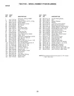
Page 29: ...und 29 532 40 15 45 Switch Seat 30 532 19 33 50 Switch Ign 33 532 41 19 33 Key Chain 34 532 11 07 12 Switch Light Reset 40 532 40 10 98 Harness Ign Dash 41 817 72 04 08 Screw Thd Cut 1 4 20 x 1 2 42 532 13 15 63 Cover Terminal 43 532 19 25 07 Solenoid 46 532 40 17 63 Gauge Serviceminder Hrmtr 55 817 06 05 12 Screw Thdrol 5 16 18 x 3 4 TYTT 71 532 40 04 49 Harness Ign 79 532 17 52 42 Socket Asm Bul...

Page 30: ...L NUMBER YTH22V46 289630 15 206 204 210 j _ 130 t 208 18 234 181 _ 5 176 176f 81 137 _234 176 130 150 25 209 181 196 36 138 36 194 236 213 183j I 68 68 chassis tex TEX GT HUSQ 68 162 181 58 189 _159 3O 228 152 189 217 189 ...

Page 31: ...ine 206 532 40 17 11 Skirt Hood Side LH Screw 5 18 18 x 3 4 207 532 19 71 98 Bezel RH Fender 208 532 19 71 99 Bezel LH Nut Lock 5 16 18 209 532 19 91 30 insert Hex Top RH Drawbar Upper 2PC Sml Fender 210 532 19 91 31 insert Hex Top LH Screw Thdrol 5 18 18 x 1 2 211 532 19 91 32 insert Hex Bottom RH Screw 10 x 0 750 212 532 19 91 33 insert Hex Bottom LH Bumper Dash 213 874 78 05 12 Bolt 5 18 18 x 3...

Page 32: ...VE TRACTOR MODEL NUMBER YTH22V46 289630 221 r_ _i 207 _ L 160 26 209 J 206 125 16 I 221 184 51 42 52 33 230 205 drive tex K46 pedal 48 rl 29 116 73 211 22 226 153 125 2O8 225 2 183 _125 222 211 166 2O5 32 ...

Page 33: ...V Groove 910 Offset 210 532 40 09 80 V Belt Drive 211 532 12 01 83 Shaft Asm Pedal Brake Control 213 532 40 31 19 Bolt Hex 5 16 18 Gr 5 214 532 42 12 63 Strap Torque 215 532 40 17 23 Bolt FinHex5 18 18uncxl 25 216 5321961 31 Rod Spring Bypass 221 532 40 31 87 Nut Lock Hex Flange 5 18 18 222 879 21 20 10 Screw 5 16 18 x 3 4 225 532 40 33 19 Screw 5 18 18 x 1 2 228 532 40 15 84 Retainer Spring 1 227...

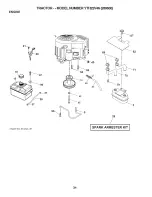
Page 34: ...ENGINE TRACTOR MODEL NUMBER YTH22V46 289630 f_F 18 _97 I I _ _ 37 engine tex_bs 2cyt_49 84 82 81 71 29 34 ...

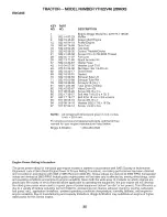
Page 35: ...your engine manufacturer listed below Briggs Stratton 1 800 233 3723 Engine Power Rating Information The gross power rating for individual gas engine models is labeled in accordance with SAE Society of Automotive Engineers code J1940 Small Engine Power Torque Rating Procedure and rating performance has been obtained and corrected in accordance with SAE J1995 Revision 2002 05 Torque values are deri...

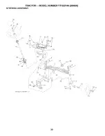
Page 36: ...TRACTOR MODEL NUMBER YTH22V46 289630 STEERING ASSEMBLY 63 19 6O 57 63 22 J J 61 4 _ __59 58 2 69 68_ steering tex HUSQHR 1 rl 67 67 36 ...

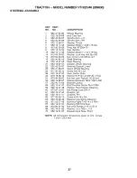
Page 37: ...7 Wheel Steering Axle Cast Iron Spindle Asm LH Spindle Asm RH Washer Thrust Washer 25 32 x 1 5 8 x 16 Ga Ring Klip T5304 75 Cap Spindle Washer 25 32 x 1 1 4 x 16 Ga Washer Lock Hvy Hlcl Spr 3 8 Nut Crown Lock 3 8 24 unf Shaft Steering Plate Steering Adapter Wheel Steering Steering Support Lower Insert Wheel Steering Screw 3 8 16 x 3 4 Gear Sector Plate Washer 9 16 ID x 2 3 80D 12 Ga Nut Hex Jam To...

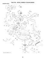
Page 38: ...MOWER DECK TRACTOR MODEL NUMBER YTH22V46 289630 195_122 j123 z195 3 117 119_ 38_ 188 189 113 144 30 38 j33 31 3O 69 21 198 21 69 24 19 46 tex It pred 11 rl 19 188 199 29 4O _119 117 27 38 ...

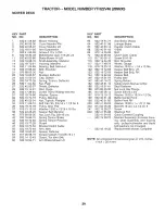
Page 39: ...lector 147 532 40 18 72 Nut Push 152 532 43 51 10 Shield Deflector 188 532 19 51 61 Rod Hinge 189 873 90 05 00 ScrewThdrol RollingWsh Hd 195 817 00 06 12 Washer Spacer 197 819 13 13 12 Pulley Mandrel 198 532 40 31 49 Nut Toplock Flanged 199 532 40 31 50 Bolt Carr Sh 3 8 18 x 1 1 2 Gr 5 200 532 41 35 24 Pulley Idler Flat 240 874 52 06 38 Washer 13 32 x 13 16 x 18 Ga 241 532 15 29 27 Keeper Belt Man...

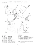
Page 40: ...ver Spring Torsion Pin Cotter 7 16 Bow Tie Lock Spring Lift Assist Washer Clear Zinc Pin Cotter 5 16 Bow Tie Lock Link Lift Susp Mower Rear 88 97 101 I I KEY PART NO NO 97 817 00 08 12 98 532 19 52 70 100 873 93 06 00 101 532 40 70 03 89 87 Key 9t may be substituted for Key 10t DESCRIPTION Screw 3 8 18 x 75 Smgml Tap R Z Link Lift Susp Front Mower Nut Center Lock 3 8 18 unc Link Asm Lift Fixed NOT...

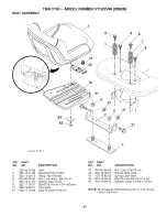
Page 41: ... unc 7 532 12 41 81 Spring Seat Cprsn 8 532 17 18 77 Bolt 5 16 18 unc x 3 4 w Sems 10 532 19 69 77 Pan Seat 21 532 17 18 52 Bolt Shoulder 5 16 18 KEY PART NO NO 37 873 80 05 00 40 532 19 76 61 41 532 19 82 00 43 874 76 06 12 44 819 13 38 12 DESCRIPTION Nut Lock 5 16 18 unc Handle Slide Seat Spring Latch Seat Bolt Fin Hex 3 8 16 unc x 3 4 Washer 13 32 x 2 3 8 x 12 Ga NOTE All component dimensions g...

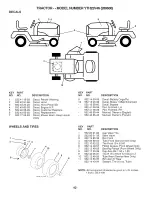
Page 42: ...Schematic Decal Bypass Pad Footrest LH Pad Footrest RH Manual Owner s English Manual Owner s French WHEELS AND TIRES 1 2 3 7 4 10 wheel art 5 9 KEY PART NO NO 1 532 05 91 92 2 532 06 51 39 3 532 13 83 36 4 532 05 99 04 5 532 10 62 22 6 532 12 49 57 7 532 12 49 59 8 532 17 50 39 9 532 42 05 31 10 532 12 49 26 11 532 13 83 37 532 14 43 34 DESCRIPTION Cap Valve Tire Stem Valve Rim Front Tube Front Se...

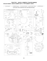
Page 43: ...LiQUiD GASKET AND THE BREATHER GASKET ARE iNTERCHANGEABLE 1330 REPAIR MANUAL 121 CARBURETOR OVERHAUL KIT 51 104 105 150 163 672 _ Jsi_ e 987 _ 1124 C _ _ 1353 1095 VALVE GASKET SET 1022 _i 12 20 358 ENGINE GASKET SET 524 F 691 _ _ 842 y 868_ t 718 50J _ 12 617 163 252 24 1013 _ _ _i _ 741 46 1027 45 lO 15 177 _ _ 524 404 D i 552A_ ii 742 _ 616 742 _ it 552A _ 552 691 750 _ 250 43 ...

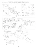
Page 44: ...NUMBER YTH22V46 289630 BRIGGS ENGINE MODEL NUMBER 407777 TYPE NUMBER 1195 B1 868 617 _ s i_zY 1022 883 i_isT i 187 601 628_ 1023 _ 1022 467 _ 1040 163 445 _ _ 573 865 1022 _6_ 1029 34i 868 d_ 4o I_ 222 188 i 216ii 44 ...

Page 45: ...PE NUMBER 1195 B1 9 2319 i i 108 C ii 1353 d bY 276 _ _M _ i 947i i 276 _ dc_i 1124_2 1128g 418 672 14LZ4_J r t 1128 _ _ _ 150 oi _ 959 i 130 i J i 987 I 1371 276 _ _ _ _ 615 o h 789 877 _ s _ 1119 _ 635 _ 220 _ _ j 334 1005 1054 _ _ 1070 1 851 783 513 668 l_II 212 505 k 45 ...

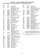
Page 46: ...9 Screen Rotating 358 694012 74 698425 Screw Rotating Screen 385 697551 75 691056 Washer Flywheel 387 808656 95 690718 Screw Throttle Valve 404 690442 98 699721 Kit Idle Speed 415 794903 104 694918 Pin Float Hinge 415A 690283 105 698537 Valve Float Needle 418 795912 108 699723 Valve Choke 431 790816 117 791501 Jet Main Standard Left 445 499486s 117A 791502 Jet Main Standard Right 447 691003 118 69...

Page 47: ...d 803 Housing Starter Service by 497595 Starter Motor Only Reference 309 i 847 499602 Dipstick Tube Assembly _ 850 100106 Sealant Liquid Used to Seal Breather Assembly and Rocker Cover 851 493880s Terminal Spark Plug 865 691012 Cover Air Guide Cylinder 1 865A 796541 Cover Air Guide Cylinder 2 865B 691015 Cover Air Guide Cylinder 3 868 _ 690968 Seal Valve 877 790544 Wire Con nector AIternator 883 6...

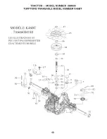
Page 48: ...R MODEL NUMBER 289630 TUFFTORQ TRANSAXLE MODEL NUMBER K46BT MODI_LE K46BT 7A646084180 LES ILLUSTRATIONS NE PEUVENT PAS REPRtESENTER EXACTEMENTE MODI_LE 115 I 53 91 116 I 60 55 83 _ 34 59 10 15 81 78 I 72 I 48 ...

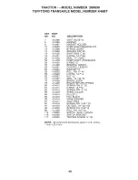
Page 49: ...R F 55 415924 WASHER 12 58 415925 ROLL PIN 6 40 59 415926 O RING 1A P14 60 415927 NUT 12 72 414407 SEAL 19 32 8 76 414408 BRAKE LEVER 78 414409 BRAKE RETURN SPRING 80 414410 SPRING PIN 5 32 81 414411 0 RING IAP12 82 414412 SPRING PIN 4 16 83 414413 SPINE COLLAR 84 414414 PULLEY L 85 414415 FAN BLACK 86 414416 WAVE WASHER 87 414417 SNAP RING 90 414418 SPRING PIN 3 0A 20 91 414419 OIL SEAL 16 22 03 ...

Page 50: ...SERVICE NOTES 50 ...

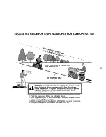
Page 51: ...lopes greater than 15 degrees Make turns gradually to prevent tipping or loss of control Exercise extreme caution when changing direction on slopes 1 Fold this page along dotted line indicated above 2 Hold page before you so that its left edge is vertically parallel to a tree trunk or other upright structure 3 Sight across the fold in the direction of hill slope you want to measure 4 Compare the a...

Page 52: ...05 26 10 JA Husqvarna Printed in the U S A ...

Reviews: