background image

Summary of Contents for 917.29939

Page 1: ... I m Owner s Manual 532 43 58 47 ...

Page 2: ...eep machine attachments and accessories in safe working condition Check shear pins engine mounting bolts and other bolts at frequent intervals for proper tightness to be sure the equipment is in safe working condition Never store the machine with fuel in the fuel tank inside a building where ignition sources are present such as hot water and space heaters clothes dryers and the like Allow the engi...

Page 3: ...n maintaining caring for and using your tiller Follow instructions under Maintenance and Storage sections of this Owner s Manual iMPORTANT THIS UNIT IS EQUIPPED WITH AN INTERNAL COMBUSTION ENGINE AND SHOULD NOT BE USED ON OR NEAR ANY UNIMPROVED FOREST COVERED BRUSH COVERED OR GRASS COVERED LAND UNLESS THE ENGINE S EXHAUST SYSTEM IS EQUIPPED WITH A SPARK ARRESTER MEETING APPLICABLE LOCAL LAWS IF AN...

Page 4: ...SEMBLY A socket wrench set will make assembly easier Standard wrench sizes are listed 1 Utility knife 1 Screwdriver 1 Pair of pliers 2 1 2 wrenches OPERATOR S POSITION See Fig 1 When right or left hand is mentioned in this manual it means when you are in the operating position standing behind tiller handles FRONT LEFT RIGHT OPERATOR S POSITION Fig 1 CONTENTS OF HARDWARE PACK 1 Manual 2 Carriage Bo...

Page 5: ...OL CABLES TINE HANDLE MOUNT i _ HANDLE COLUMN CARRIAGE BO_ FLANGE LOCKNUT iNSTALL DEPTH STAKE ASSEMBLY See Fig 3 Loosen nut _ Insert stake support between engine bracket halves with stake spring down Bolt stake support to engine brackets with bolts lock washers and nuts Tighten securely Tighten nut _ Depth stake must move freely If it does not loosen support bolt ENGINE BRACKET HALVES NUT A DEPTH ...

Page 6: ...CAUTION ENGINE ENGINE FAST SLOW CHOKE FUEL OIL OR WARNING ON OFF FORWARD TINE CONTROL REVERSE TINE CONTROL CHOKE CONTROL CONTROL DEPTH STAKE SHIELD RECOIL STARTER HANDLE 0 Fig 4 MEETS ANS SAFETY REQUIREMENTS Our tillers conform to the safety standards of the American National Standards Institute FORWARD TINE CONTROL Engages tines in forward direction REVERSE TINE CONTROL Engages tines in reverse d...

Page 7: ...D Squeeze forward tine control to handle REVERSE With forward tine control OFF up position pull back and hold reverse tine control TILLING The speed and depth of tilling is regulated by the position of the depth stake and wheel height The depth stake should always be below the wheels for digging It serves as a brake to slow the tiller s forward motion to enable the tines to penetrate the ground Al...

Page 8: ...o not store spill or use gasoline near an open flame IMPORTANT WHEN OPERATING IN TEMPERATURES BELOW 32 F 0 C USE FRESH CLEAN WINTER GRADE GASOLINE TO HELP INSURE GOOD COLD WEATHER STARTING CAUTION Alcohol blended fuels called gasohol or using ethanol or methanol can at tract moisture which leads to separation and formation of acids during storage Acidic gas can damage the fuel system of an engine ...

Page 9: ...enriches the soil Depending on the climate rainfall and wind it may be advisable to till the soil at the end of the growing season to further condition the soil Soil conditions are importantfor proper tilling Tines will not readily penetrate dry hard soil which may contribute to excessive bounce and difficult handling of your tiller Hard soil should be moistened before tilling however extremely we...

Page 10: ...e To receive full value from the warranty operator must maintain tiller as instructed in this manual Some adjustments will need to be made periodically to properly maintain your tiller All adjustments in the Service and Adjustments section of this manual should be checked at least once each season Once a year you should replace the spark plug clean or replace air filter and check tines and belt fo...

Page 11: ...5 hours of continuous use Add SAE 30 motor oil or equivalent Tighten oil filler plug securely each time you check the oil level TO CHANGE ENGINE OiL See Figs 11 and 12 Determine temperature range expected before oil change All oil must meet API service classification SG SL Be sure tiller is on level surface Oil will drain more freely when warm Catch oil in a suitable container Remove drain plug Ti...

Page 12: ...aged SPARK PLUG Replace spark plugs at the beginning of each tilling sea son or after every 50 hours of use whichever comes first Spark plug type and gap setting is shown in PRODUCT SPECIFICATIONS on page 3 of this manual TRANSMISSION Your transmission is sealed and will only require lubrication if it is serviced CLEANING Do not clean your tiller when the engine and transmission are hot We do not ...

Page 13: ...L NUTS ALSO 2 ON LEFT SIDE OF TILLER Fig 15 TINE ARRANGEMENT Your outer tines can be assembled in several different ways to suit your tilling or cultivating needs i CAUTION Tines are sharp Wear gloves or other protection when han dling tines NORMAL TILLING 26 INCH PATH See Fig 16 Assemble holes _ in tine hubs to holes B in tine shaft HAIRPIN CLIP INNER TINE Fig 16 13 MID WIDTH TILLING 24 INCH PATH...

Page 14: ... Slowly pull recoil starter handle while observing tines Tines should rotate forward If tines do not rotate inner wire of control cable is too loose Loosen cable clip and pull cable up to remove slack and retighten clip Recheck in ON position and adjust if necessary NOTE If ON position check required adjustment recheck OFF position adjustment to insure tines do not rotate when control is OFF up TI...

Page 15: ...ice outlet TO ADJUST CARBURETOR The carburetor has been preset atthe factory and adjustment should not be necessary However engine performance can be affected by differences in fuel temperature altitude or load If the carburetor does need adjustment contact your nearest authorized service center department IMPORTANT NEVER TAMPER WITH THE ENGINE GOVERNOR WHICH IS FACTORYSET FOR PROPER ENGINE SPEED ...

Page 16: ...LE IN STORAGE Drain the fuel tank Start the engine and let it run until the fuel lines and carburetor are empty Never use engine or carburetor cleaner products in the fuel tank or permanent NOTE Fuel stablizer is an acceptable alternative in minimizing the formation of fuel gum deposits during storage Add stabilizer to gasoline in fuel tank or storage container Always follow the mix ratio found on...

Page 17: ...ait several minutes before attempting to start 4 Clean or replace air cleaner cartridge 5 Drain fuel tank and carburetor and refill tank with fresh gasoline 6 Remove fuel tank and clean 7 Make sure spark plug wire is seated properly on plug 8 Replace spark plug or adjust gap 9 Make necessary adjustments 1 Place throttle control in FAST position 2 Clean or replace air cleaner cartridge 3 Replace sp...

Page 18: ...p HandJe 01 29 Nut Flange 05 08 Bolt Carriage 5 18 18 x 3 4 14 78 Assembly Panel and Tube 85 32 Lever Control Tine 85 55 Pin Pivot 81 71 Cable Asm Reverse 00 59 Retainer Ring KEY NO 35 38 38 5O PART NO DESCRiPTiON 872 01 05 20 Bolt 5 18 18 x 2 1 2 873 97 05 00 Locknut Flange 5 18 18 unc 532 43 55 87 Assembly Handle Column 532 18 15 80 Clip Routine Dual NOTE All component dimensions given in U S in...

Page 19: ...e Idler Bolt Hex Head 3 8 16 x 1 3 4 Guard Belt Washer 9 32 x 5 8 x 16 Ga Nut Cap 1 4 20 Bolt Carriage 1 4 20 x 3 4 V Belt Forward Motion V Belt Reverse Ring Retainer Key Square Sheave Transmission Flat Bolt Belt Guard Ring Klip lO 112 32 18 KEY PART NO NO 21 873 35 22 532 16 23 532 17 24 874 76 25 532 10 26 873 35 27 873 22 28 810 04 29 532 10 30 823 20 31 532 10 32 532 15 41 532 18 42 532 13 14 ...

Page 20: ...4 16 532 12 Bolt Hex Head 5 16 18 x 3 4 17 532 42 Nut Hex 5 16 18 19 532 00 Washer Lock 5 16 20 873 68 Locknut w washer 3 8 16 21 874 76 Clip Hairpin 22 873 80 Support Depth Stake R H 24 873 97 Stake Depth 25 819 17 Pin Clevis Bolt Hex 3 8 16 x 1 3 4 Support Depth Stake L H 53 88 Spring Stake 11 17 Bolt Shoulder 70 25 Wheel 91 90 Bracket Wheel 06 00 Locknut Crown 3 8 16 05 16 Bolt Hex Head 5 16 18...

Page 21: ...5 tine_ipb_3 KEY PART NO NO DESCRIPTION 1 532 15 69 34 Tine Outer R H 2 532 00 31 46 Retainer Spring 3 532 15 69 32 Tine Inner R H KEY PART NO NO 4 532 15 69 31 5 532 15 69 33 6 532 00 49 29 DESCRIPTION Tine Inner L H Tine Outer L H Rivet Pan Hd Drilled 1 4 Dia 21 ...

Page 22: ...8 18 x 3 1 4 Washer 13 32 x 13 18 x 11 Locknut 3 8 16 Shield Tine Bracket Engine R H Bracket Engine L H Nut Hex 5 16 18 Bolt Hex Head 5 16 18 x 2 5 Transmission KEY NO 14 18 17 18 19 2O 10 transmission 12 PART NO DESCRIPTION 532 00 91 73 Spacer Split 819 09 14 12 Washer 9 32 x 7 8 x 12 Ga 819 09 20 18 Washer 9 32x 1 1 4 x 18 Ga 810 04 04 00 Washer Lock 1 4 874 61 04 12 Bolt Hex 1 4 28 x 3 4 Gr 5 E...

Page 23: ...2 43 29 87 5 532 11 08 14 8 532 12 00 76 9 532 42 29 72 10 532 40 41 43 11 532 43 22 78 532 43 58 47 532 43 58 48 DESCRiPTiON Decal Logo Decal Logo Decal Logo Decal Panel Control Inst Decal Hand Placement Decal Warning Rotating Tines Decal Tine Shield Decal Tank Decal Air Cleaner Manual Owner s English Manual Owner s French 23 ...

Page 24: ...E MODEL NUMBER 121002 TYPE NUMBER 1380 B8 J 48 SHORT BLOCK 415 _ 12 22 742 _3 746 _ 21 15A _ 24 0 _0_O_OR SM_NU_L I_2_R_L_C_M_N_NG N_ I I_0_RM_NU_LI 11 lS_ 1026 332 146 741 13 _ _ 46 365_ 951 190 __ 635 1029 869 601 45 _k_j 1026 S _ 1022 914A 24 ...

Page 25: ...NGINE MODEL NUMBER 121002 TYPE NUMBER 1380 B8 1270 163 6921 130 _ 95 _ _ q _186 51_i 1133 1 _ _ _ _ 276 _ _ 621 663 _ 281 190_ 188 562 _ _ J 677 _ 635 334 2_ 356 163 161 445 S_ _ _ o_l o 1005 1070 _ _ 455 332 _ 23 300 613 883 832 836 _ _ 25 ...

Page 26: ...90 BRIGGS ENGINE MODEL NUMBER 121002 TYPE NUMBER 1380 B8 358 ENGINE GASKET SET 20 163 51 883_ 1022 1022 104 _ 51 121 CARBURETOR OVERHAUL KIT 127 0 163 633 _ 137 276 63j 633A 1211 1210 I 65 456 689 j 597_ I 1036 EMISSIONS LABEL 26 ...

Page 27: ...arter Rope 597 691696 65 699228 Screw Rewind Starter 601 791850 95 691636 Screw Throttle Valve 608 795930 97 690024 Shaft Throttle 613 699209 98 398185 Kit Idle Speed 615 692576 104 691242 Pin Float Hinge 616 692547 108 692567 Valve Choke 619 699230 109 790624 Shaft Choke 621 692310 117 690048 Jet Main Standard 632 693408 118 497315 Jet Main High Altitude 633 693867 121 792006 Kit Carburetor Overh...

Page 28: ... Valve Fuel Shut Off 968 791082 Cover Air Cleaner 972 697779 Tank Fuel 975 790559 Bowl Fuel 993 694088 Gasket Cylinder Head Plate 1005 692592 Fan Flywheel 1022 691890 Gasket Rocker Cover 1023 499924 Cover Rocker 1026 790287 Rod Push 1029 797443 Arm Rocker 1034 691343 Guide Push Rod 1036 Label Emissions Available from a Briggs Stratton Authorized Dealer 1058 277040 Operator s Manual 1070 699201 Scr...

Page 29: ...SERVICE OTES 29 ...

Page 30: ...SERVICE NOTES 3O ...

Page 31: ...SERVICE OTES 31 ...
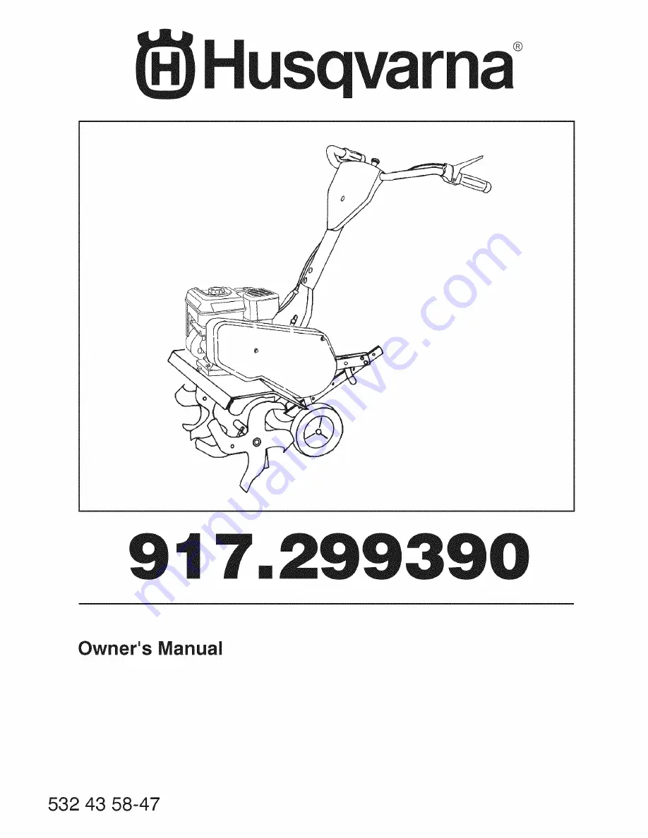
Page 32: ...separate warranty with product at time of purchase SECTION 2 HUSQVARNA S OBLIGATIONS UNDERTHE WARRANTY Husqvarna will repairor replace defective components without charge for parts or labor if a component fails because of a defect in material orworkmanship during the warranty period SECTION 3 ITEMS NOT COVEREDBYTHIS WARRANTY The following items are not covered by thiswarranty 1 Normalcustomer main...

Reviews: