


6
ASSEMBLY
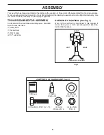
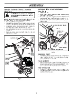
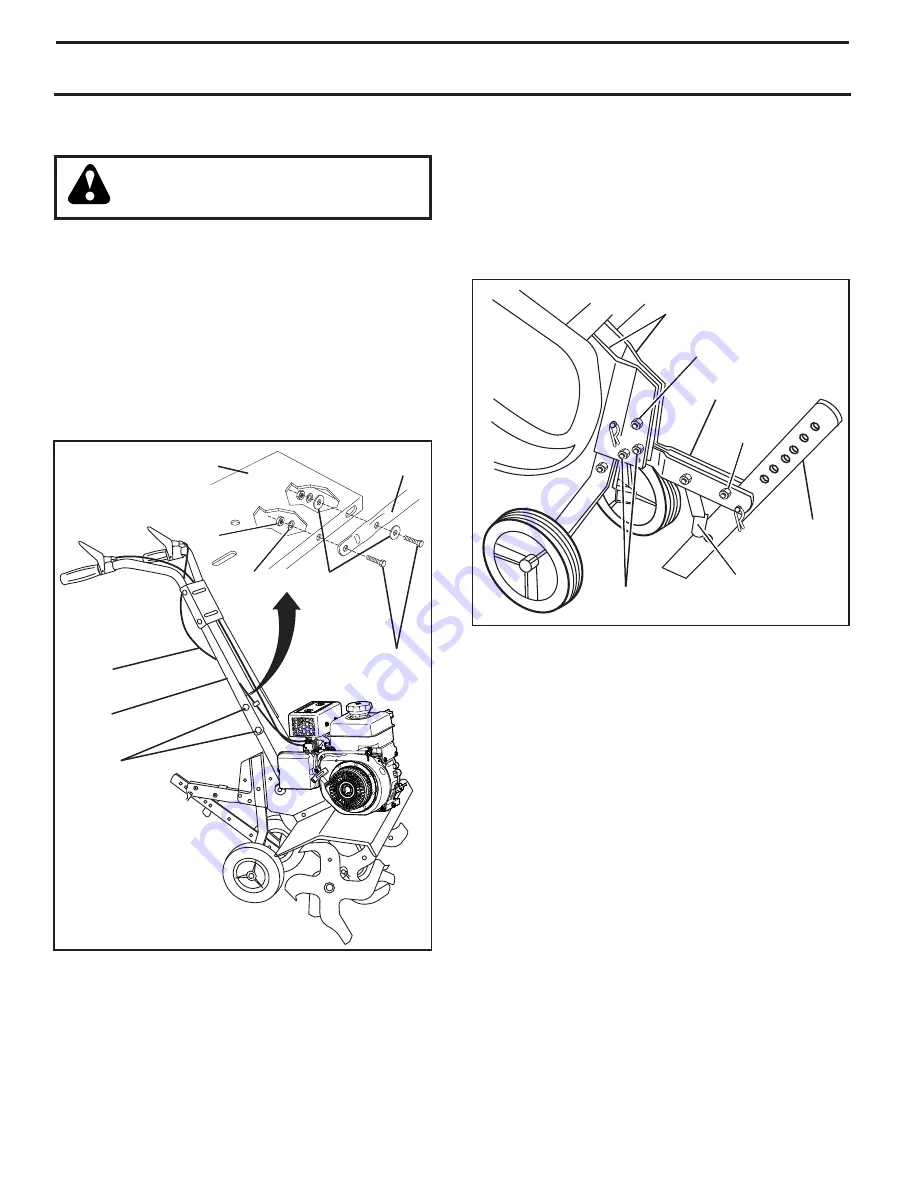
INSTALL DEPTH STAKE ASSEMBLY
(See Fig. 3)
•
Loosen nut “A”.
• Insert stake support between engine bracket halves
with stake spring down.
• Bolt stake support to engine brackets with bolts, lock
washers and nuts. Tighten se curely. Tighten nut “A”.
• Depth stake must move freely. If it does not, loosen
support bolt.
HANDLE HEIGHT
• Handle height may be adjusted to better suit operator.
(See “HANDLE HEIGHT” in the Service and Ad just-
ments section of this manual).
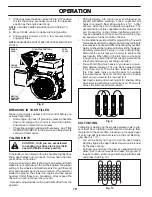
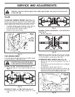
TILLING WIDTH
• Tilling width may be adjusted to better handle your
tilling con di tions (See “TINE ARRANGEMENT” in the
Ser vice and Adjustments section of this manual).
TINE OPERATION
• Check tine operation before first use. (See “TINE
OPERATION CHECK” in the Service and Adjustments
section of this manual).
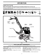
UNPACK CARTON & INSTALL HANDLE
(See Fig. 2)
CAUTION: Be careful of exposed sta ples
when handling or disposing of carton-
ing material.
IMPORTANT:
WHEN UNPACKING AND AS SEM BLING TILLER,
BE CAREFUL NOT TO STRETCH OR KINK CABLE(S).
• Cut cable ties securing handles.
• Slowly lift handle as sem bly up, route cable(s) as shown
and align han dle holes with handle panel hole and slot.
• Loosely assemble hardware as shown. Repeat for
opposite side. Tight en all hardware se cure ly.
• Cut cable ties securing tiller to skid and remove tiller
from skid.
• Remove screws securing depth stake to skid and
discard the screws.
depth_s
tak
e_4
DEPTH
STAKE
HEX BOLTS,
LOCK WASH ERS, AND HEX NUTS
DEPTH STAKE
SUPPORT
NUT “A”
ENGINE BRACK ET HALVES
STAKE SPRING
Fig. 3
SUPPORT
BOLT
Fig. 2
TILLER
HANDLE
CABLE
HANDLE
PANEL
BOLTS
HAN DLE PANEL
TILLER
HANDLE
HEX BOLTS
5/16-18 x
1-1/4"
FLAT
WASHERS
LOCK
WASH ER
NUT
Summary of Contents for 96083001100
Page 19: ...19 SERVICE NOTES ...
Page 20: ...05 09 18 SR Printed in U S A ...


