background image

505 29 00-57  04.21.08  CL                                                                                                                      PRINTED IN U.S.A.

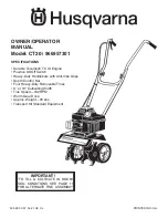
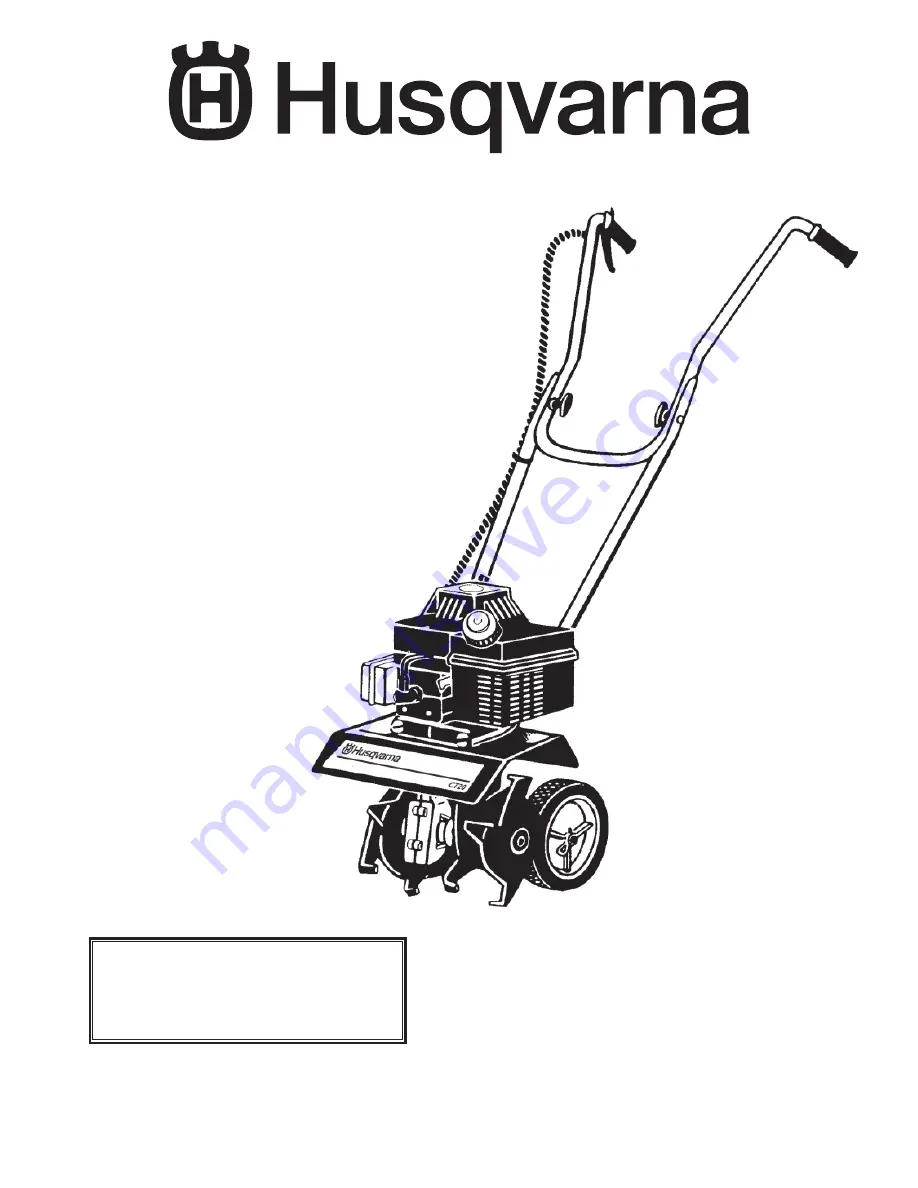
OWNER/OPERATOR

MANUAL

Model: CT20

 / 966957301

SPECIFICATIONS

• Durable Tecumseh TC 

III


Engine

• Positive On/Off Switch

• Heavy-Duty Handlebars with Anti-Vibe Grips

• Depth Control Bar

• Four Heavy-Duty Removable Tines

• 6’’ or 10” Cultivating Width

• Tine Speed—162 RPM

• Worm Gear Drive

• Approx. Weight—25 Lbs.

• Transport Kit Standard Equipment

"TO TILL & CULTIVATE IN ROCKY 

SOIL CONDITIONS SEE PAGE 11 

FOR ALTERNATE TINE ASSEMBLY"

IMPORTANT!

Summary of Contents for 966957301

Page 1: ...gine Positive On Off Switch Heavy Duty Handlebars with Anti Vibe Grips Depth Control Bar Four Heavy Duty Removable Tines 6 or 10 Cultivating Width Tine Speed 162 RPM Worm Gear Drive Approx Weight 25 Lbs Transport Kit Standard Equipment TO TILL CULTIVATE IN ROCKY SOIL CONDITIONS SEE PAGE 11 FOR ALTERNATE TINE ASSEMBLY IMPORTANT ...

Page 2: ...uel to a running engine or to a hot engine c Fill fuel tank outdoors with extreme care Never fill fuel tank indoors d Replace gasoline cap securely and clean up spilled fuel before restarting 5 Before starting engine be sure that the throttle lever is released so that the centrifugal clutch is not engaged 6 NEVER attempt to make any adjustments while the engine is running except when recommended O...

Page 3: ...Inc 21 NEVER operate this machine when you are under the influence of alcohol drugs or medication 22 DO NOT touch engine parts which may be hot from operation Allow parts to cool before inspecting cleaning or repairing this machine 23 The operation of any powered machine can result in foreign objects being thrown by high speed rotating parts ALWAYS WEAR SAFETY GLASSES OR OTHER EYE PROTECTION WHEN ...

Page 4: ... Illustrated Parts Lists 13 21 Warranty Back Cover IMPORTANT THESE PRECAUTIONARY DECALS ARE STRATEGICALLY PLACED ON YOUR UNIT FOR YOU THE USER PLEASE READ CAREFULLY 2 ª4 ª 0 2 4 23ª 5 sª 7 4 4 5 4 42 3 sª 0 3 3 3 49 6 3 0 sª 6 2 7 2 2 5 3425 4 5 43 4 0 2 4 4 3 sª 3 54 4 5 4 3 2 2 0 23 sª 2 33 02 0 2 9 n 4 7 2 3 4 2 7 29 sª 7 937 2 3 2 9 02 4 4 sª 0 2 0 43 934 23 4 3 34 05 34 2 3 0 24 4ª 4 2 44 ª 4...

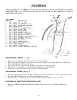
Page 5: ...o hold upper handle in place 2 Secure carriage bolts with two 2 curved washers and plastic tee knobs 3 Next firmly tighten lower loc nuts against handlebars until all handlebar play has been eliminated ASSEMBLY DRAG STAKE WHEEL TRANSPORT 1 Mount drag stake onto bracket with clevis pin and hairpin cotter pin See Fig 20 on page 16 for assembly sequence Fig 1 ITEM ORDER NO NO DESCRIPTION 1 505 29 00 ...

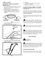
Page 6: ...used Read the fuel instructions in the manual and or on the engine Always store the fuel to be used in this machine in a properly marked container that is approved for such use Always wear goggles or face shield for eye protection It is advisable to wear protective head gear These precautions are used to prevent the possibility of being struck by objects thrown from the rotating tines 4 Push 2 ter...

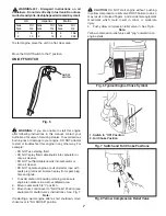
Page 7: ...s into carburetor or onto air cleaner DO NOT operate engine or pull on starter rope with spark plug removed Fuel can spray from spark plug hole and ignite To avoid carbon monoxide poisoning make sure engine is outdoors in a well ventilated area Move rocker switch to I position Move choke control lever to Full Choke Position see equipment manufacturer s instructions See Fig 7 1 2 3 Note If restarti...

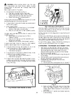
Page 8: ...rt after following steps 1 thru 9 contact your Authorized Tecumseh Servicing Dealer DO NOT attempt to start or troubleshoot this engine in any other way Fig 9 Starter Cord Handle Location Fig 10 Choke Lever Position 2 3 1 Full Choke 1 2 Choke No Choke 1 2 3 After the engine is started and has run for a few seconds move the choke lever as far as it will go in the opposite direction from the startin...

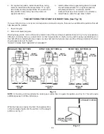
Page 9: ...crew opening Push gun or applicator against the opening so as to seal the nozzle of the gun or applicator against the casting embossment Apply grease until you see the grease at the air vent hole 6 Re install air vent screw and fill hole screw 7 Re install dust cap 8 Place a few drops of oil on tine shaft before installing tines 9 Wearing heavy gloves re install tines For tine pattern refer to Fig...

Page 10: ...our unit are deter mined from the operator s position behind the unit Note that all four tines of this unit are different and must be installed correctly or tiller will not function properly Tines will wear and become quite sharp Be very careful when replacing tines If tines are being replaced due to wear all four tines should be replaced as a set See Fig 15 ALWAYS MOVE SWITCH TO O POSITION AND RE...

Page 11: ...hut off engine 2 Disconnect spark plug wire Wearing heavy gloves remove tines and re install in one of the two stony soil patterns shown in Fig 16 If you experience difficulty in removing tines as a result of dirt or other foreign matter on shaft you may wish to apply a penetrating oil on the shaft When re installing the tines make sure tine shaft and tine hubs are clean and free of foreign materi...

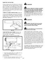
Page 12: ...ER NEVER TAMPER WITH ENGINE GOVERNOR WHICH IS FACTORY SET FOR PROPER ENGINE SPEED OVER SPEEDING ENGINE MAY INCREASE THE DANGER OF PERSONAL INJURY AND WILL VOID ENGINE WARRANTY If you think the engine governed high speed needs adjusting contact your nearby authorized Tecumseh Service Dealer who has the proper equipment and experience to make neces sary adjustments DANGER NEVER STORE UNIT WITH GASOL...

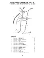
Page 13: ...6 Throttle Cable 1 7 505 29 00 07 Wire Assembly 1 8 505 29 00 08 Handlebar Upper 1 9 505 29 00 09 Knob Plastic Handlebar 2 10 505 29 00 10 Washer Curved Knob 2 11 505 29 00 11 Screw Curved Hd 5 16 18 x 1 1 2 2 12 505 29 00 12 Handlebar Lower L H 1 13 505 29 00 13 Handlebar Lower R H 1 16 505 29 00 14 Nut 1 4 20 2 17 505 29 00 10 Washer Curved 4 18 505 29 00 15 Screw 1 4 20 x 4 1 2 2 23 505 29 00 5...

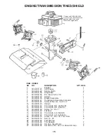
Page 14: ...sher Thrust 2 10 505 29 00 26 Bearing Needle Thrust 1 11 505 29 00 27 Washer Adaptor 1 12 505 29 00 28 Shaft Worm 1 13 505 29 00 29 Washer Thrust 1 14 505 29 00 30 Washer Thrust 2 15 505 29 00 31 Shaft Tine w Worm Wheel 1 17 505 29 00 32 Felt Seal 2 19 505 29 00 33 Dirt Cap Silver Metal 2 20 505 29 00 34 Set Screw 10 32 x 1 4 2 21 505 29 00 35 Bracket Assy Drag Stake 1 22 505 29 00 36 Screw 1 4 20...

Page 15: ...00 43 Hairpin 2 11 505 29 00 44 Tine Hub R H Outbrd D 1 12 505 29 00 45 Tine Hub R H Inbrd C 1 13 505 29 00 36 Screw 1 4 20 x 1 2 15 505 29 00 32 Felt Seal 2 16 505 29 00 46 Tine Hub L H Inbrd B 1 17 505 29 00 47 Tine Hub L H Outbrd A 1 22 505 29 00 37 Screw 1 4 20 x 7 8 Thrd From 6 23 505 29 00 14 Nut 1 4 20 2 24 505 29 00 63 Fuel Mix Cup 25 505 29 00 48 Tine Spacers 2 26 505 29 00 33 Dirt Cap Si...

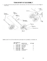
Page 16: ... WHEEL BAR UP ARROW 5 WHEEL 2 CLEVIS PIN 7 LOCK NUT 3 8 16 LOCK PIN 6 WASHER 2 ITEM ORDER NO NO NO DESCRIPTION QTY REQ 1 505 29 00 49 Hex Bolt 3 8 16 x 8 1 2 505 29 00 50 Inner Collar 2 3 505 29 00 51 Outer Collar 2 4 505 29 00 52 Wheel Bar 1 5 505 29 00 53 Wheel 2 6 505 29 00 54 Washer 2 7 505 29 00 55 Lock Nut 3 8 16 1 505 29 00 56 CT20 Decal 1 NOTE PLEASE FOLLOW THE DIRECTIONS SHOWN ABOVE TO AS...

Page 17: ...17 NOTES ...

Page 18: ...18 NOTES ...

Page 19: ...19 NOTES ...

Page 20: ...ON 2 HUSQVARNA S OBLIGATIONS UNDER THE WARRANTY Husqvarna will repair or replace defective components without charge for parts or labor if a component fails because of a defect in material or workmanship during the warranty period SECTION 3 ITEMS NOT COVERED BY THIS WARRANTY The following items are not covered by this warranty 1 Normal customer maintenance items which become worn through normal re...

Reviews: