background image

13

SERVICE

SERVICE

SERVICE

SERVICE

SERVICE

SERVICE ASSISTANCE -
REPLACEMENT PARTS

To retain the quality of your mower, use genuine
HUSQVARNA replacement parts only. Contact
your local HUSQVARNA dealer for parts and
service assistance. For the correct part or
information for your particular mower, always
mention model and serial number. We recom-
mend returning your mower to an authorized
HUSQVARNA dealer on a yearly basis for
inspection and addition of any new devices
which might upgrade the performance and
safety of your mower. For engine parts and
service, look in the yellow pages for the engine
manufacturer's dealers under the heading
engines - gasoline.

WARNING

BEFORE PERFORMING SERVICE ON THE

MOWER TURN ENGINE OFF, CLOSE THE

FUEL VALVE,  AND ALLOW ENGINE TO

COOL. DISCONNECT THE SPARK PLUG

WIRE.  IF THE MOWER IS TO BE RAISED

OR TILTED, MAKE SURE TO SECURE THE

MOWER IN PLACE.

MODULE SYSTEM

The interlock modules function is to prevent the
engine from starting if the blade and/or traction
systems are engaged. It also causes engine
shutdown if the operator falls from, or attempts
to leave the operator position while the blades or
traction drives are engaged. After the engine
starts, the operator must hold either the left or
right O.P. lever down before engaging the
blades or shifting the transmission into gear. If
neither O.P. lever is held the engine will stop.

INTERLOCK SAFETY SYSTEM

Check the function of the safety electrical
system on a regular basis.

1. Engine must kill if blades are engaged without
O.P. levers held down.

2. Engine must kill if transmission is taken out of
neutral without holding down O.P. levers.

NOTE

ALL MOWERS SHOULD BE TILTED WITH

THE CARBURETOR SIDE UP

CAUTION

DO NOT BYPASS THE INTERLOCK SWITCHES

THEY ARE FOR YOUR PROTECTION! CHECK

THE OPERATOR PRESENCE SYSTEM DAILY

ALONG WITH THE TRACTION DRIVE SWITCHES

AND BLADE SWITCH FOR PROPER OPERATION.

REPAIR IMMEDIATELY IF A

PROBLEM IN THE SYSTEM IS FOUND. DO NOT

OPERATE MOWER IN A DAMAGED CONDITION.

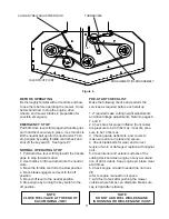
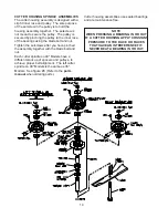
BLADES

If blades are in good condition, sharpen at an
angle of 22 to 28 degrees about 2-1/2" in from
the tips.

NOTE

AFTER SHARPENING, CHECK BLADES FOR

PROPER BALANCE, IF NEEDED CORRECT BAL-

ANCE TO PREVENT EXCESSIVE VIBRATION

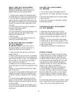
CUTTING DECK SERVICE

If mower is cutting improperly, check the follow-
ing:
1. Ground speed - too fast for proper cutting.
Shift to a lower gear.

2. Engine speed - Increase engine speed.

3. Cutting height - too low for ground/grass
conditions. Adjust to higher cut.

4. Blade spacers - not positioned properly on all
blade shafts. Visually inspect and replace or
adjust as necessary.

5. Front casters - spacers not in correct rela-
tionship with rear axle. Adjust as necessary.

6. Belt slippage - causing bad cutting pattern or
uneven cut. Adjust belt tension

7. Tire pressure - uneven tire pressure can
cause an uneven cut from one side of the deck
to the other. Equalize tire pressure.

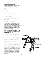
3. Engine must not start unless blades are off
and transmission is in the neutral position.

4. Do not operate the mower if the interlock
safety system allows operating or starting in any
unsafe condition.

Summary of Contents for 968999117

Page 1: ...MANUAL NO 539106457 REV IR 09 20 01 Operators Manual Models 968999117 W3613ETS 968999120 W4815ETS Please read these instructions carefully and make sure you understand them before using the machine ...

Page 2: ...s accomplished If the traction lever is squeezed even tighter the brake will be applied to that wheel and a tighter more abrupt turn is ac complished LEARN HOW TO USE THESE IMPORTANT STEERING BRAKE CONTROLS As an additional safety feature these mowers are equipped with an Operators Presence System This is an electrical interlock safety system which is activated by depressing either one or both of ...

Page 3: ...3 Table of Contents SAFETY 4 SETUPANDADJUSTMENTS 5 11 OPERATION 11 12 SERVICE 13 15 MAINTENANCE CHART 16 ...

Page 4: ...ards such as holes stumps sprinkler heads etc 4 Do not operate the mower when barefoot or wearing open shoes Always wear substantial footwear and long pants 5 Fill gasoline tank before starting the engine Only use an approved gasoline container Do not smoke near open gasoline containers Do not fill gasoline tank indoors or when engine is running or hot Wipe off any spilled gasoline before starting...

Page 5: ...ardware Setup Adjustments LINKAGE INSTALLATION 1 Install drive linkage into the hole in the idler arm on the inside of the tank support The drive linkages are fastened to the drive levers on the handle assembly Secure the drive linkages to the idler arm by inserting a retaining ring through the small hole in the end of the drive linkage 2 Install shifter to transmission with 1 4 x 1 screws The shi...

Page 6: ...er of rear deck raise the jack slightly so axle adjustment bolts may be removed 5 With the jack raise or lower the rear deck to the desired position using the chart to ensure proper height Reinstall the axle adjustment bolts and tighten A tapered punch may be used to help align the holes See figure 1 NOTE It may be necessary to readjust drive and brake linkages NOTE To achieve the best quality cut...

Page 7: ...TION A POSITION B POSITION C POSITION D AXLE PIVOT BOLTS PLACE JACK HERE Figure 1 REAR AXLE HEIGHT ADJUSTMENT LOOSEN BOLTS EACH SIDE CASTER SWIVEL 1 2 SPACERS MACHINERY BUSHING CASTER HEIGHT ADJUSTMENT Figure 2 Setup Adjustments ...

Page 8: ...3 4 4 3 1 4 3 1 2 3 3 4 4 4 1 4 3 1 2 3 3 4 4 4 1 4 4 1 2 3 3 4 4 4 1 4 4 1 2 4 3 4 4 4 1 4 4 1 2 4 3 4 5 4 3 2 1 0 4 3 2 1 0 4 3 2 1 0 4 3 2 1 0 4 3 2 1 0 4 3 2 1 0 4 3 2 1 0 4 3 2 1 0 1 To quickly achieve small changes in cutting heights move the spacers from under the cutter housing to above the cutter pulley Each spacer moved will give an additional 1 4 of cutting height 0 1 2 3 5 3 4 4 B A D ...

Page 9: ...t with the O P lever when the operator presence levers are released BLADE SWITCH ADJUSTMENT The blade engagement switch can be adjusted by loosening the screws on the blade engage ment bracket and moving the switch up or down The blade switch should be adjusted so the plunger is fully depressed when the engage ment lever is fully disengaged ADJUSTMENTS DRIVE BELTS For all drive belts tension shoul...

Page 10: ...e blades should come to a stop from maximum speed within 7 seconds after disengaging BLADE ENGAGEMENT LEVER The blade engagement lever needs to be adjusted so the lever does not come in contact with control panel when the lever is in the off position To adjust remove the clevis pin from the yoke and adjust by turning the yoke The clevis pin connects the blade engagement lever to the yoke and the y...

Page 11: ...ral position 6 Stop engine by turning the key switch to the off position NOTE CLOSE FUEL VALVE AT THE END OF EACH MOWING JOB PRE START CHECKLIST Make the following checks and perform the services as required before each start up 1 If required make cutting height adjustments and drive linkage adjustments Refer to pages 6 7 and 8 2 Check tires for proper inflation front caster tire pressure to be 50...

Page 12: ... NOTE DO NOT engage the blades at full rpm To extend belt life engage and disen gage belts at 1 2 throttle 8 Depress one operator presence lever and shift transmission to the desired gear 9 Unlock the drive levers by pushing the neutral bail down out of the neutral slots Slowly release both drive levers at the same time to begin forward motion 10 The steering system of this mower uses individual r...

Page 13: ...lectrical system on a regular basis 1 Engine must kill if blades are engaged without O P levers held down 2 Engine must kill if transmission is taken out of neutral without holding down O P levers NOTE ALL MOWERS SHOULD BE TILTED WITH THE CARBURETOR SIDE UP CAUTION DO NOT BYPASS THE INTERLOCK SWITCHES THEY ARE FOR YOUR PROTECTION CHECK THE OPERATOR PRESENCE SYSTEM DAILY ALONG WITH THE TRACTION DRI...

Page 14: ...hten the setscrews after you have pinched the assembly together with the blade bolt and nut Each cutter spindle on 48 Models have a different stack up of spacers and pulleys to achieve proper belt alignment The left cutter spindle on 48 Models is the same as 36 Models See figure 8 Refer to the parts manual when ordering parts Cutter housing assemblies use sealed bearings and are maintenance free N...

Page 15: ...guides located around the pulleys on the front deck Belt guides are 5 16 bolts and must be loosened to remove the belt 8 Remove belt 9 To replace belt reverse the procedure and make any needed adjustments to belt guides or belt tension AUXILIARY BELT REPLACEMENT 48 MOWERS 1 Loosen the auxiliary belt adjusting rod To relieve tension on the belt See figure 6 on page 11 2 Remove belt guides from the ...

Page 16: ...se Caster Shafts Daily Lube With Grease Engine Oil Level Daily Fill as Needed Rear Wheels Daily Lube With Grease Brake Arms Daily Lube With Grease Engagement Bellcrank Daily Lube With Grease Transmission Shafts Weekly Lube With Grease Blades Weekly Replace if Damaged EngineAir Filters Every 25 Hours See Engine Manual Engine Oil Change Every 100 Hours See Engine Manual Linkages Adjustments 100 Hour...

Page 17: ...17 Model Number Serial Number Date of Purchase Dealer Information Notes ...

Page 18: ......

Reviews: