12
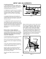
By moving the levers an equal amount forward
or back the machine will move in a straight line
in that direction. FIG - 10
Movement of either lever forward will cause the
right or left wheel to rotate in a forward direction.
To stop movement pull both levers into the
neutral position.
To turn right while moving in a forward direction
pull the right lever back towards the neutral
position, this will slow the rotation of the right
wheel and cause the machine to turn in that
direction.
To turn left while moving in a forward direction
pull the left lever back towards the neutral
position, this will slow the rotation of the left
wheel and cause the machine to turn in that
direction.
To zero turn pull one lever back beyond neutral
while holding the other slightly ahead of neutral.
NOTE: The direction of the zero turn will be
determined by which lever is pulled back beyond
neutral. Thus left lever back, left zero turn and
opposite for right zero turn.
Use extra care
when using this maneuver the machine can
spin very rapidly if one lever is positioned
to far ahead of the other.
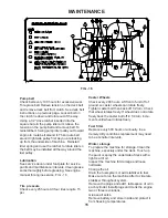
Blade engagement switch located on the con-
sole is engaged by pulling up on the switch and
pushed down to disengage. FIG - 11
Choke control is located on the console. To
choke engine pull knob push to release. FIG - 11
Throttle control is located on the console. Used
to control engine RPM. FIG - 11. Some models
have an intergated choke located on the throttle
control. Choke position for these models is
maximum forward on the throttle control.
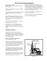
Parking brake is located on the left side of the
machine and directly in front of the fuel tank. Pull
the lever back to engage the brake and push
lever forward to release the brake.
OPERATING INSTRUCTIONS
Key Switch
Throttle
Choke
Blade
Engagement
Motion Control Lever Pattern
(Right Side)
FIG - 10
FIG - 11
NOTE:
Associated choke on some models.
Key switch is located on the console. Used to
start the machine. NOTE: Do not run the starter
for more than 5 seconds at a time. If the engine
will not start, wait about 10 seconds before
trying again. FIG - 11
Summary of Contents for 968999204
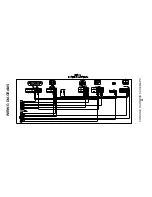
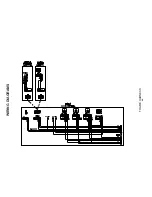
Page 20: ...20 WIRING DIAGRAMS CONSOLE HARNESS SCHEMATIC ...
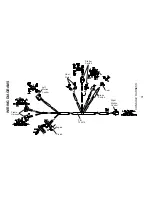
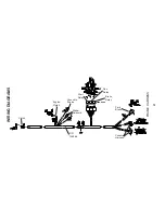
Page 22: ...22 WIRING DIAGRAMS FRAME HARNESS ...
Page 23: ...23 ...
Page 24: ......


