19
Run engine full throttle to make sure wheels do
not rotate. Readjust if any rotation occurs.
Repeat the whole process for the opposite side
and tighten the nuts against the ball joints.
Turn machine off.
Reinstall the seat rod and check the wiring har-
ness to the seat safety switch for a good connec-
tion and return the seat to the normal position.
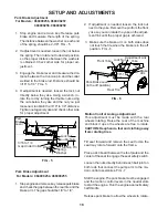
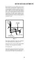
Turn Here
To Adjust
Loosen Here
Loosen Here
(Lt. Hand Thds.)
Motion
Control
Lever
FIG - 7
Begin with either side and put the motion control
lever into the neutral position. Adjust the motion
control linkage by rotating the double nuts in the
proper direction until the wheel stops rotating.
FIG - 7 Move the motion control lever forward
then into the neutral position and place it into the
neutral slot. The wheel must be stopped com-
pletely at this point. Now do the same in reverse
and release the lever. The lever should return to
neutral on its own.
Pump
Arm
SETUP AND ADJUSTMENTS
Summary of Contents for 968999207 / iZ5223KAA
Page 2: ...2 2004 Husqvarna All right reserved Beatrice NE Printed U S A ...
Page 28: ...28 WIRING DIAGRAMS ...
Page 29: ...29 WIRING DIAGRAMS ...
Page 30: ......

