English - 65
When the main switch is set to position
1
after
replacing a main circuit board, a new start-up
sequence commences, which includes entering
a new PIN code.
5.8 Replacing the MMI circuit board
1. Disassemble the body. See
5.2.1 Disassembling
the body on page 57
.
2. Disassemble the chassis. See
5.2.2
Disassembling the chassis on page 57
.
3. Disassemble the display cover. See
5.2.3 Disassembling the display cover on
page 58
.
4. Disconnect all connections from the
connectors on the MMI circuit board.
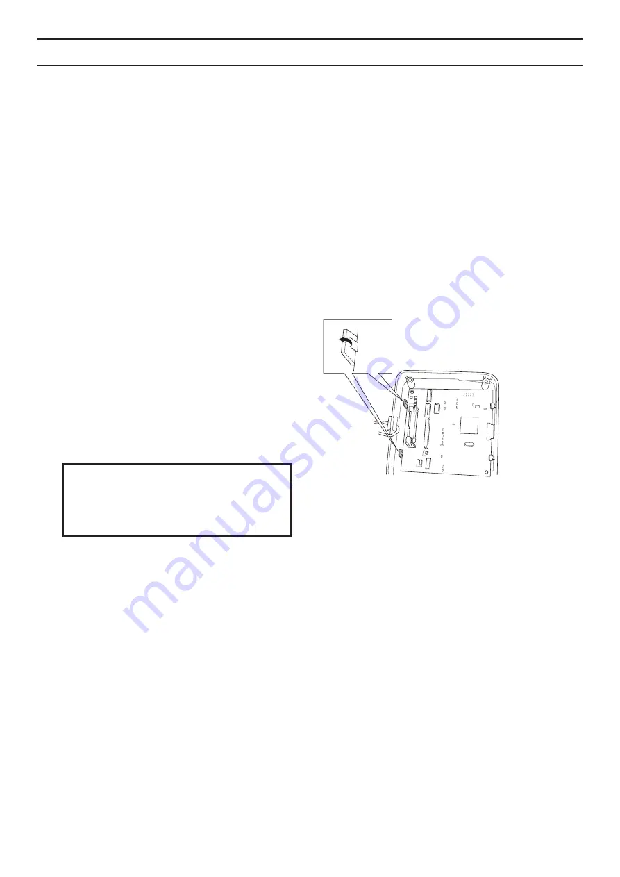
5. The MMI circuit board is secured to the
display cover by means of two snap-on
fasteners. Carefully bend away the snap-on
fasteners and lift the MMI circuit board in the
edge on which the snap-on fasteners are
located.
6. Remove the MMI circuit board.
7. Fit a new MMI circuit board. Carefully bend
away the snap-on fasteners to make it easier
to fit the MMI circuit board.
Only touch the edges of the circuit board.
Never touch the board’s components and
pin terminals.
IMPORTANT INFORMATION
8. Reconnect all cables to the MMI circuit board.
9. Refit the display cover, chassis and body.
10. Put the main switch in position
1
and connect
the mower to Autocheck EXP to program the
MMI circuit board. See
4.3.4 Programming on
page 47
.
5. REPAIR INSTRUCTIONS
Summary of Contents for Automower 320
Page 1: ...HUSQVARNA AUTOMOWER 320 330X TECHNICAL MANUAL ...
Page 2: ......


