English - 68
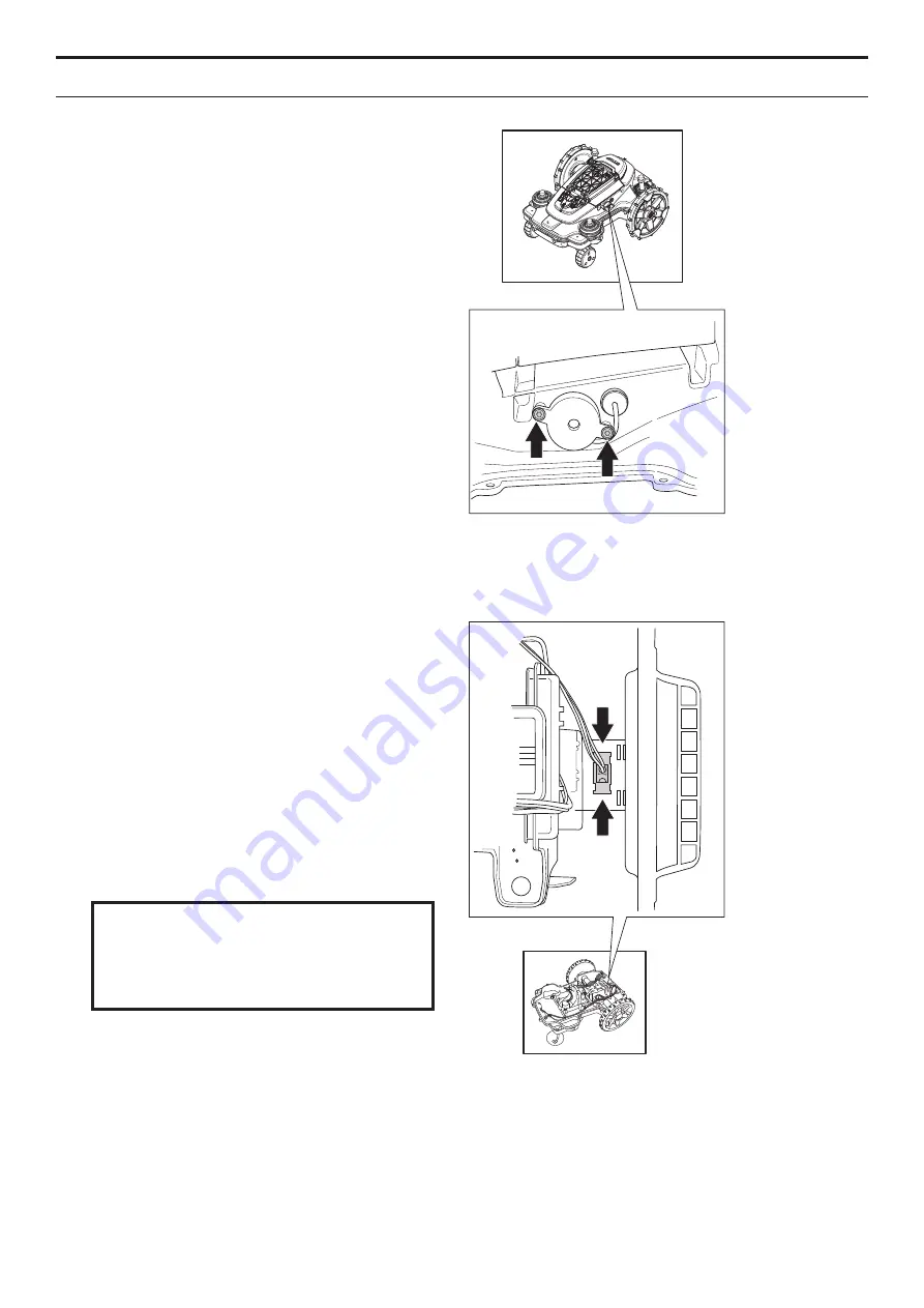
5.11 Replacing the buzzer
1. Disassemble the body. See
5.2.1
Disassembling the body on page 57
.
2. Disassemble the chassis. See
5.2.2
Disassembling the chassis on page 57
.
3. Loosen the two screws (Torx 20) holding the
buzzer in position.
4. Disconnect the buzzer connectors from the
MMI circuit board and remove the buzzer
from the chassis.
5. Fit the new buzzer. Be careful when fitting the
rubber seal through the chassis to prevent
any moisture getting through the opening.
6. Connect the buzzer’s connector to the MMI
circuit board.
7. Refit the chassis and body.
5.12 Replacing the main switch
1. Disassemble the body. See
5.2.1
Disassembling the body on page 57
.
2. Disassemble the chassis. See
5.2.2
Disassembling the chassis on page 57
.
3. Disassemble the main circuit board. See
5.7 Replacing the main circuit board on
page 63
.
4. Press the snap-on fasteners together on the
main switch and press the main switch out
through the opening in the lower chassis
section.
5. Fit the new main switch together with the
new gasket in the opening and press the
main switch into the opening. Ensure that the
locking barbs are securely attached to make
it completely sealed.
Check that the main switch is installed so that
the digit
1
is positioned to the left and
0
to the
right, viewed from behind.
IMPORTANT INFORMATION
6. Refit the main circuit board and connect all
the connections.
7. Refit the chassis and body.
5. REPAIR INSTRUCTIONS
Summary of Contents for Automower 320
Page 1: ...HUSQVARNA AUTOMOWER 320 330X TECHNICAL MANUAL ...
Page 2: ......


