English - 70
5.14 Replacing the sensors
5.14.1 Front loop sensors
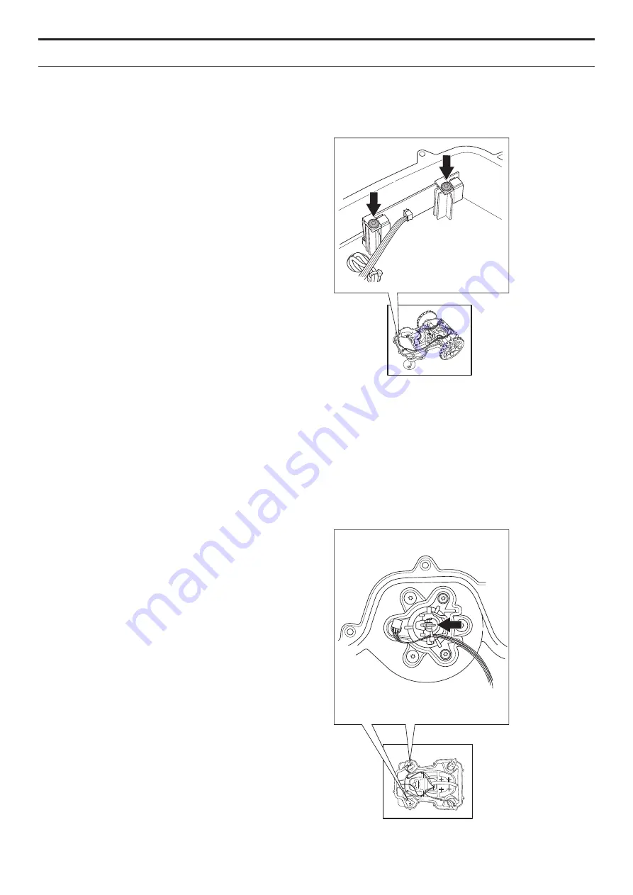
The front loop sensors are mounted on the front
sensor circuit board. The sensors cannot be replaced
separately. The entire front sensor circuit board must
be replaced as a unit.
1. Disassemble the body. See
5.2.1
Disassembling the body on page 57
.
2. Disassemble the chassis. See
5.2.2
Disassembling the chassis on page 57
.
3. Disconnect the cable from the front sensor
circuit board. Note: Always pull the connector
and NOT the cable.
4. Unscrew the two screws (Torx 20) which
secure the holders for the front sensor circuit
boards.
5. Fit the new front sensor circuit board and
reconnect the cable.
6. Refit the chassis and body.
5.14.2 Rear loop sensors and tilt sensor
The rear loop sensors and tilt sensor are part of the
main circuit board. The sensors cannot be replaced
separately. The entire main circuit board must be
replaced as one unit. See
5.7 Replacing the main
circuit board on page 63
.
5.14.3 Lift sensors
The magnet on the collision column must be fitted
correctly if the lift sensors are to work. If this is not the
case, the components in the front collision column
must be replaced. See
5.19 Replacing the front
collision columns on page 75
.
To replace the lift sensor circuit board:
1. Disassemble the body. See
5.2.1
Disassembling the body on page 57
.
2. Disassemble the chassis. See
5.2.2
Disassembling the chassis on page 57
.
5. REPAIR INSTRUCTIONS
Summary of Contents for Automower 320
Page 1: ...HUSQVARNA AUTOMOWER 320 330X TECHNICAL MANUAL ...
Page 2: ......


