background image

• Always use original accessories and spare parts.

Accessories and spare parts that are not approved

by the manufacturer, can cause serious injury or

death.

• Replace damaged, worn or broken parts.
• Only do the maintenance as given in this operator's

manual. Let an approved service center do all other

servicing.

• Remove all tools from the product before you start

the engine after maintenance. Loose tools or tools

attached to rotating parts can eject and cause injury.

• After maintenance, do a check of the vibration level

in the product. If it is not correct, speak to an

approved service center.

• Let an approved service center do servicing on the

product regularly.

Assembly

Introduction

WARNING: Read and understand the safety

chapter before you assemble the product.

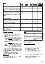
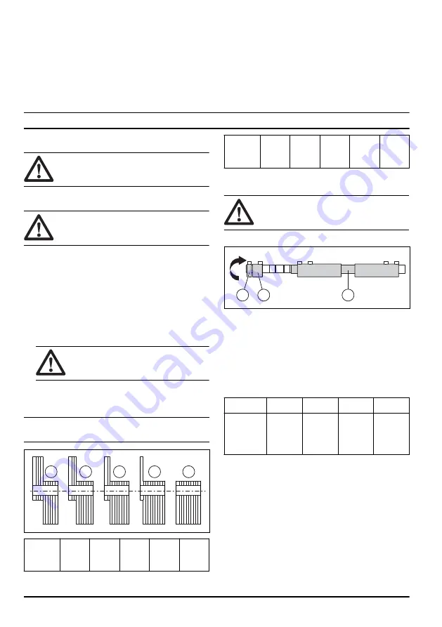
To adjust the centrifugal force (BE 20)

WARNING: Disconnect the power source

before you adjust the centrifugal force.

1. Remove the screws from the covers for the eccentric

weights. There is 1 cover on each side of the drive

unit.

2. Remove the covers for the eccentric weights.
3. Remove the nuts that hold the eccentric weights.

The available positions are identified in the table and

on the covers.

4. Turn the eccentric weights 180° to adjust the

centrifugal force.

CAUTION: Do the same adjustment at

each end of the drive unit.

5. Attach the eccentric weights.
6. Install the covers. Make sure that the cover seals are

in good condition.

Note: The centrifugal force is set at position 4 at the

factory.

5

4

3

2

1

Number

of

weights

1

2

3

4

5

Centrifu-

gal

force, N

920

1850

2770

3690

4620

To adjust the centrifugal force (BE 30)

WARNING: To prevent accidental start, stop

the engine and remove the spark plug cap

before you adjust the centrifugal force.

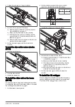
1. Remove the cap.

C

B

A

2. Loosen the screws that hold the eccentric weights

(A) and (B).

3. Turn the eccentric weights (A) and (B) 180° to adjust

the centrifugal force.

4. Tighten the screws that hold the eccentric weights

(A) and (B).

5. Install the cap. Make sure that the O-rings are

installed correctly.

Weights

C

A+C

B+C

A+B+C

Centrifugal

force, N

@3600

min

-1

1920

2140

2400

2620

To install the drive unit on the beam

(BE 20)

It is recommended to adjust the centrifugal force before

you install the drive unit on the beam. Refer to 

To adjust

the centrifugal force (BE 20) on page 8

.

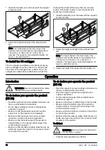
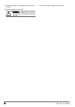
1. Put the beam on level ground.
2. Put the drive unit at the center of the beam.

8

1299 - 001 - 14.04.2020

Summary of Contents for BD 32

Page 1: ...BE 20 BE 30 BD 32 BD 42 BD 52 BD 62 EN Operator s manual 2 21 ...

Page 2: ...oline BE 30 drive unit The drive unit is used together with a BD beam These BD doubble beams are vibrating beams intended for compaction and levelling of concrete during its placement The BD beams have 2 parallel aluminum beams and are available in different dimensions Intended use The product is for professional operation only The product is used for compaction of concrete to make areas of concre...

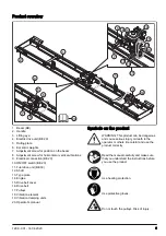
Page 3: ...ive unit BE 30 12 Shaft 13 Type plate 14 Engine 15 Drive belt cover 16 Drive belt 17 Pulleys 18 Vibration element 19 Vibration damping units 20 Operator s manual Symbols on the product WARNING This product can be dangerous and cause serious injury or death to the operator or others Be careful and use the product correctly Read the manual carefully and make sure that you understand the instructions...

Page 4: ...proved by the manufacturer the product has an accessory that is not from the manufacturer or not approved by the manufacturer the product is not repaired at an approved service center or by an approved authority Safety Safety definitions Warnings cautions and notes are used to point out specially important parts of the manual WARNING Used if there is a risk of injury or death for the operator or b...

Page 5: ...ects from the work area Before you go away from the product stop the product and disconnect the power source Make sure that the power outlet voltage agrees with the voltage that is given on the rating plate of the product Make sure that clothes long hair and jewelry do not get caught in moving parts Do not sit on the product Do not hit the product Make sure that you or other persons cannot get cau...

Page 6: ...halation can cause health problems Exhaust fumes that you can see or smell also contain carbon monoxide Do not use a combustion engine product indoors or in areas that do not have sufficient airflow Do not breathe the exhaust fumes Make sure that the airflow in the work area is sufficient This is very important when you operate the product in trenches or other small work areas where exhaust fumes ...

Page 7: ...make sure that fuel and fuel fumes cannot cause damage Drain the fuel in an approved container outdoors and away from sparks and flames Electrical safety WARNING Read the warning instructions that follow before you use the product The power plug must agree with the power outlet Do not do modifications to the plug Do not use adapter plugs with grounded products Power plugs without modifications and...

Page 8: ...ghts The available positions are identified in the table and on the covers 4 Turn the eccentric weights 180 to adjust the centrifugal force CAUTION Do the same adjustment at each end of the drive unit 5 Attach the eccentric weights 6 Install the covers Make sure that the cover seals are in good condition Note The centrifugal force is set at position 4 at the factory 5 4 3 2 1 Number of weights 1 2...

Page 9: ...ore you install the drive unit on the beam Refer to To adjust the centrifugal force BE 30 on page 8 1 Put the beam on level ground 2 Put the vibration element of the drive unit 200 mm 7 9 in A from the center of the beam A 3 Tighten the screws A Torque to 68 Nm A 4 Examine the movement of the beam a Start the product Refer to To start the fuel drive unit BE 30 on page 11 b Make sure that the beam ...

Page 10: ...erate the product BE 20 Read the operator s manual carefully and make sure that you understand the instructions Do the daily maintenance Refer to Maintenance schedule on page 12 Make sure that the electrical connection and the power cord on the product are not damaged Make sure that the power cord can move freely along the concrete surface during operation Make sure that the bottom edge of the pro...

Page 11: ...e switch on the electrical connector to change to the opposite direction To start the fuel drive unit BE 30 1 Open the fuel valve 2 Set the choke control in the correct position a If the engine is cold close the choke b If the engine is warm or the ambient temperature is high open the choke 3 Make sure that the throttle control is set to idle speed 4 Set the engine ON OFF switch to ON 5 Pull the s...

Page 12: ...p the electric drive unit BE 20 1 Set the power switch to OFF 2 Disconnect the power cord from the power source WARNING Always disconnect the power cord from the power source when the product is not in operation To stop the fuel drive unit BE 30 1 Move the throttle control to the idle speed position 2 Set the engine ON OFF switch to OFF The engine stops 3 Move the fuel valve to the OFF position Ma...

Page 13: ...ctric drive unit CAUTION Before you clean a fuel drive unit with a high pressure washer put a cover on the engine No water must come on the carburetor the fuel tank or the generator Clean the external surfaces of the engine of a fuel drive unit with water but not a high pressure washer Clean the shafts but do not point the water at the bearings Tilt the product to clean the bottom side Remove grea...

Page 14: ... flanges with a press tool or a mallet 10 Install the flanges and the rotor CAUTION Be careful when you install the rotor The stator winding can become damaged 11 Install the eccentric weights and the covers 14 1299 001 14 04 2020 ...

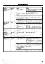
Page 15: ...n nectors and cables Replace damaged parts The tension screws cannot be turned Electric and fuel There is water from the concrete in the product sections Use penetrating oil on the tension screws The tension screws are loose or missing Electric and fuel The tension screws are worn Replace the tension screws The beam is not straight Electric and fuel The rubber bearings on the stretching screw are ...

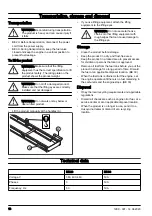
Page 16: ... eyes WARNING Do not use metal hooks chains or other lifting equipment with rough edges that can cause damage to the lifting eye Storage Clean the product before storage Keep the product in a dry and frost free area Keep the product in a locked area to prevent access for children or persons that are not approved Remove all fuel from the fuel tank before you put the product in storage for a long pe...

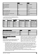
Page 17: ...ues of other products tested in accordance with the same directive or standards These declared values are not suitable for use in risk assessments and values measured in individual work places may be higher The actual exposure values and risk of harm experienced by an individual user are unique and depend upon the way the user works in what material 1 As specified by the engine manufacturer The po...

Page 18: ...the product is used as well as upon the exposure time and the physical condition of the user and the condition of the product 18 1299 001 14 04 2020 ...

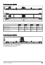
Page 19: ...n B 520 20 5 520 20 5 520 20 5 520 20 5 Length mm in C 3200 34 10 5 1 3 4200 34 13 8 1 3 5200 34 17 0 1 3 6200 34 20 3 1 3 Product dimensions BE 30 A The height A is 541 mm 21 2 in for all beams The width and length are the same as for BE 20 Refer to Product dimensions BE 20 on page 19 1299 001 14 04 2020 19 ...

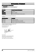
Page 20: ...complies fully with the following EU directives and regulations Directive Regulation Description 2006 42 EC relating to machinery 2014 30 EU relating to electromagnetic compatibility 2011 65 EU relating to restriction of hazardous substances and that the following harmonized standards and or technical specifications are applied EN 12649 2008 A1 2011 Partille 2020 03 05 Martin Huber R D Director Co...

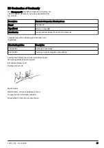
Page 21: ...20 and onwards complies fully with the following EU directives and regulations Directive Regulation Description 2006 42 EC relating to machinery 2014 30 EU relating to electromagnetic compatibility and that the following harmonized standards and or technical specifications are applied EN 12649 2008 A1 2011 Partille 2020 03 05 Martin Huber R D Director Concrete Surfaces Floors Husqvarna AB Construc...

Page 22: ...22 1299 001 14 04 2020 ...

Page 23: ...1299 001 14 04 2020 23 ...

Page 24: ...www husqvarnacp com Original instructions 1140662 26 2020 04 22 ...

Reviews: