background image

To do the troweling operation

1. Start the motor. Refer to 

To start the product on

page 7

.

2. Turn the blade adjustment knob until there is tension

in the cable.

3. Move the product across the concrete surface.

a) Adjust the blade adjustment knob as necessary

during operation.

CAUTION: Do not increase the blade

angle too much and too quickly. The

increased pressure from the product can

cause damage to the concrete surface.

4. Stop the product and remove it from the concrete

surface.

5. Wait until the concrete is sufficiently set.
6. Do the procedure again and again until the concrete

surface has a satisfactory finish and is fully set.

Note: The period of time between troweling operation is

calculated from how quickly the concrete sets.

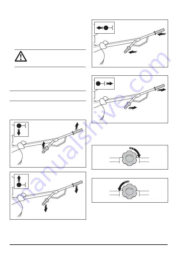
To move the product in different

directions

• To turn to the left, lift the handles.

• To turn to the right, push the handles down.

• To move the product forward, push the handles

forward.

• To move the product rearward, pull the handles

rearward.

To adjust the blade angle

The blade angle is adjusted gradually.
1. To increase the blade angle, turn the blade

adjustment knob clockwise.

2. To decrease the blade angle, turn the blade

adjustment knob counterclockwise.

8

1132 - 001 - 06.04.2020

Summary of Contents for BG 245E

Page 1: ...BG 245E EN Operator s manual 2 17 ...

Page 2: ... prevents scratches on the wall The product can be used with the optional accessory floating disc Intended use The product is for professional operation only The product is used to give a smooth surface on wet concrete floors Do not use the product for other tasks Product overview 15 1 2 4 8 7 6 5 12 11 10 9 3 13 14 1 Blade adjustment knob 2 Quick stop handle 3 Start button 4 Electrical box 5 Rati...

Page 3: ...mpliance with applicable EC directives Note Other symbols decals on the product refer to special certification requirements for some markets Rating plate 3 4 9 11 8 10 5 2 1 6 7 1 IP classification 2 Product type 3 Product weight 4 Rated power 5 Production year 6 Serial number 7 Product number 8 Voltage V 9 Manufacturer 10 Current A 11 Frequency Hz Safety labels Remove the floating disc before you...

Page 4: ...l drugs or medicine Always be careful and use your common sense This product produces an electromagnetic field during operation This field can under some circumstances interfere with active or passive medical implants To decrease the risk of serious injury or death we recommend persons with medical implants to speak to their physician and the medical implant manufacturer before operating this prod...

Page 5: ...tion of the product or at other times If you have symptoms and continue to operate the product the symptoms can increase or become permanent If these or other symptoms occur get medical aid Numbness loss of feeling tingling pricking pain burning throbbing stiffness clumsiness loss of strength changes in skin color or condition Symptoms can increase in cold temperatures Use warm clothing and keep y...

Page 6: ...NG Read the warning instructions that follow before you use the product Do not use a product with defective safety devices Do a check of the safety devices regularly If the safety devices are defective speak to your Husqvarna service agent Quick stop function The blades stop immediately when you release the quick stop handle To do a check of the quick stop function 1 Start the motor Refer to To st...

Page 7: ...an extension cable B C A 2 Connect the extension cable to a power outlet 230 V 10 A fuse WARNING Make sure that the power outlet has RCD protection 3 Pull the quick stop handle B until it is against the handlebar Keep the quick stop handle in this position during operation 4 Push the start button C 5 During operation hold the handlebar and the quick stop handle with two hands Working techniques Th...

Page 8: ...rete is sufficiently set 6 Do the procedure again and again until the concrete surface has a satisfactory finish and is fully set Note The period of time between troweling operation is calculated from how quickly the concrete sets To move the product in different directions To turn to the left lift the handles To turn to the right push the handles down To move the product forward push the handles ...

Page 9: ...ne by the operator The instructions are not given in this operator s manual X The instructions are given in this operator s manual Maintenance Daily be fore use Daily after use After the first 20 h Monthly each 200 h Yearly each 500 h Make sure that there are no oil leaks Clean the product X Make sure that nuts and screws are tightened Lubricate the blade shafts after the product is cleaned X X Ma...

Page 10: ...he tension is correct when the V belt can be pushed in 3 mm 0 12 in with a force of 20 N 4 5 lbf 6 Install the V belt cover To set the product in maintenance position WARNING Disconnect the power cord from the power source to prevent accidental start The maintenance position is used for all maintenance procedures in the blade area below the product Tilt the product forward until it is stable on th...

Page 11: ...a puller if the blade assembly is not easy to remove 3 Remove the pressure plate 4 Remove the protection ring A and the needle bearing B B A 5 Clean the surfaces of all parts and lubricate carefully Replace damaged parts 6 Lubricate the needle bearing with grease Refer to Technical data on page 15 for correct type of grease 7 Assemble in the opposite sequence To replace the blades WARNING Before y...

Page 12: ...2 Remove the screws A and replace the blades B A B 3 Lubricate the blade shafts Refer to To lubricate the blade shafts on page 11 12 1132 001 06 04 2020 ...

Page 13: ... the blades are bent or defective Replace damaged blades 1 or more of the blades do not move correct ly in the hub Remove the blades Clean and lubricate all contact surfaces The pressure plate is bent or defective Replace the pressure plate The blade adjustment system is defective 1 or more of the blades do not move correct ly in the hub Remove the blades Clean and lubricate all contact surfaces T...

Page 14: ...uct Attach the lifting equipment to the lifting eye WARNING Do not use metal hooks chains or other lifting equipment with rough edges that can cause damage to the lifting eye To lift the product manually hold it at the handlebar A and the support frame for maintenance position B B A CAUTION Do not lift the product at the protection ring Storage Clean the product before storage Keep the product in ...

Page 15: ...motor manual or the web site of the motor manufacturer Noise emissions Sound power level Lw measured dB A rel 1pW 1 102 Sound pressure level Lp at the operators ear dB A 2 86 Vibration levels 3 Vibration three axes values level ah m s2 3 7 Weights for options Floating disc kg lbs 16 35 3 Floating disc mm in 610 24 Trowel blades four units kg lbs 9 19 8 Trowel blade mm in 600 23 6 Protection ring m...

Page 16: ...values and risk of harm experienced by an individual user are unique and depend upon the way the user works in what material the product is used as well as upon the exposure time and the physical condition of the user and the condition of the product Product dimensions G H C B D A E F A Height with handle folded mm in 729 28 7 E Height at lifting point on the lifting eye mm in 643 25 3 B Length wi...

Page 17: ...lies fully with the following EU directives and regulations Directive Regulation Description 2006 42 EC 2014 30 EU 2011 65 EU relating to machinery relating to electromagnetic compatibility relating to restriction of hazardous substances and that the following harmonized standards and or technical specifications are applied EN 12649 2008 A1 2011 Partille 2019 12 06 Martin Huber R D Director Concre...

Page 18: ...18 1132 001 06 04 2020 ...

Page 19: ...1132 001 06 04 2020 19 ...

Page 20: ...www husqvarnacp com Original instructions 1140654 26 2020 04 17 ...

Reviews: