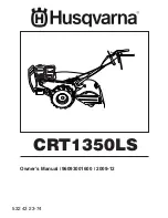
background image

CRT1350LS

Owner's Manual

 / 96093001600 / 2009-12

532 43 23-74

Summary of Contents for CRT1350LS

Page 1: ...CRT1350LS Owner s Manual 96093001600 2009 12 532 43 23 74 ...

Page 2: ...uipment Never allow adults to operate the equipment without proper instruction Keep the area of operation clear of all persons par ticularly small children and pets PREPARATION Thoroughly inspect the area where the equipment is to be used and remove all foreign objects Disengage all clutches and shift into neutral before starting the engine motor Donotoperatetheequipmentwithoutwearingadequate oute...

Page 3: ...USTION ENGINE AND SHOULD NOT BE USED ON OR NEAR ANY UNIMPROVED FOREST COVERED BRUSH COVERED OR GRASS COVERED LAND UNLESS THE ENGINE S EXHAUST SYSTEM IS EQUIPPED WITH A SPARK ARRESTER MEETING APPLICABLE LOCAL LAWS IF ANY IFASPARKARRESTERISUSED ITSHOULDBEMAINTAINED IN EFFECTIVE WORKING ORDER BY THE OPERATOR IN THE STATE OF CALIFORNIA A SPARK ARRESTER IS REQUIRED BY LAW SECTION 4442 OF THE CALIFORNIA...

Page 4: ... been assembled at the factory with exception of those parts left unassembled for shipping purposes To ensure safe and proper operation of your tiller all parts and hardware you assemble must be tightened securely Use the correct tools as necessary to insure proper tightness Fig 1 FRONT OPERATOR S POSITION LEFT RIGHT 1 Hairpin Clip 1 Carriage Bolt 3 8 16 UNC x 1 Grade 5 1 Center Locknut 3 8 16 UNC...

Page 5: ...ACK HANDLE LOCK VIEWED FROM R H SIDE OF TILLER handles_17 HANDLE ASSEMBLY UP POSITION LOOSEN HANDLE LOCK LEVER TO MOVE TIGHTEN HANDLE LOCK LEVER TO HOLD handles_34 CARRIAGE BOLT SLOT GEARCASE HANDLE LOCK FLAT WASHER HANDLE LOCK LEVER PIVOT BOLT LOCKNUT HANDLE BASE Fig 5 Rotate handle assembly down Insert rear carriage bolt first with bolt head on L H side of tiller and loosely assemble locknut See...

Page 6: ...ip through hole of shift rod to secure Fig 7 Fig 6 END OF CLUTCH CABLE CONTROL BAR CONTROL BAR BRACKET CONTROL BAR BRACKET CLUTCH CABLE ATTACH CLUTCH CABLE See Fig 6 Hook spring of clutch cable through hole in control bar bracket CHECK TIRE PRESSURE The tires on your unit were overinflated at the factory for shipping purposes Correct and equal tire pressure is important for best tilling performanc...

Page 7: ...NTS Our tillers conform to the safety standards of the American National Standards Institute CHOKE CONTROL Used when starting a cold engine DEPTH STAKE Controls depth at which tiller will dig DRIVE CONTROL BAR Used to engage tines LEVELING SHIELD Levels tilled soil RECOIL STARTER HANDLE Used to start the engine SHIFT LEVER Used to shift transmission gears SHIFT LEVER INDICATOR Shows which gear the...

Page 8: ...iller movement HARD TO SHIFT GEARS Brieflyengagedrivecontrolbarandreleaseorrocktiller forward and backward until are able to shift gears DEPTH STAKE See Fig 10 The depth stake can be raised or lowered to allow you more versatile tilling and cultivating or to more easily transport your tiller Fig 9 TILLING See Fig 11 Release depth stake pin Pull the depth stake up for increased tilling depth Place ...

Page 9: ... run out of fuel it will take extra pulls of the recoil starter to move fuel from the tank to the engine Make sure spark plug wire is properly connected Move shift lever indicator to N neutral position Place throttle control in FAST position Turn fuel shut off valve 1 4 turn to open position Move choke control to choke position Grasp recoil starter handle with one hand and grasp tiller handle with...

Page 10: ...oreplanting Loose unpackedsoilhelps root growth Best tilling depth is 4 to 6 10 15 cm A tiller will also clear the soil of unwanted vegetation The decomposition of this vegetable matter enriches the soil Depending on the climate rainfall and wind it may be advisable to till the soil at the end of the growing season to further condition the soil You will find tilling much easier if you leave a row ...

Page 11: ...evel Check tine operation Check for loose fasteners LUBRICATION Keep unit well lubricated See LUBRICATION CHART c SAE 30 OR 10W 30 MOTOR OIL d REFER TO MAINTENANCE ENGINE SECTION e EP 1 GREASE LUBRICATION CHART c WHEEL HUB d ENGINE c IDLER BRACKET c LEVELING SHIELD HINGES c DEPTH STAKE PIN e RH GEAR CASE GREASE FITTIG MAINTENANCE SCHEDULE FILL IN DATES AS YOU COMPLETE REGULAR SERVICE Check Engine ...

Page 12: ...vel more frequently to avoid possible engine damage from running low on oil Change the oil after every 25 hours of operation or at least once a year if the tiller is not used for 25 hours in one year Check the crankcase oil level before starting the engine and after each five 5 hours of continuous use Add SAE 30 motor oil or equivalent Tighten oil filler plug securely each time you check the oil l...

Page 13: ...ECLEANER COVER AIR CLEANER CARTRIDGE SPARK PLUG Replace spark plugs at the beginning of each tilling sea son or after every 50 hours of use whichever comes first Spark plug type and gap setting is shown in PRODUCT SPECIFICATIONS on page 3 of this manual TRANSMISSION Once a season lubricate the right hand side gear case grease fitting with 1 oz of EP 1 Grease CLEANING Do not clean your tiller when ...

Page 14: ... Maintain 20 pounds of tire pressure If tire pressures are not equal tiller will pull to one side Keep tires free of gasoline or oil which can damage rubber TO REMOVE WHEEL See Fig 21 Place blocks under transmission to keep tiller from tipping Remove hairpin clip and clevis pin from wheel Remove wheel and tire Repair tire and reassemble CLEVIS PIN HAIRPIN CLIP Fig 21 HEX BOLT AND WASHER HAIRPIN CL...

Page 15: ... IDLER PULLEY NOTE POSITION OF BELT TO GUIDES Check belt adjustment as described below Replace belt guard Reposition wheel and replace clevis pin and hairpin clip Fig 23 GROUND DRIVE BELT ADJUSTMENT See Fig 23 For proper belt tension the extension spring should have about 5 8 inch stretch when drive control bar is in ENGAGED position This tension can be attained as follows Loosen cable clip screw ...

Page 16: ...ed tine edges will rotate rearward from above TRANSMISSION TINE TINE 3 1 2 MAX Fig 26 TINE REPLACEMENT See Figs 24 25 and 26 CAUTION Tines are sharp Wear gloves or other protection when han dling tines A badly worn tine causes your tiller to work harder and dig more shallow Most important worn tines cannot chop and shred organic matter as effectively nor bury it as deeply as good tines A tine this...

Page 17: ...uretor does need adjustment contact your nearest authorized service center department IMPORTANT NEVER TAMPER WITH THE ENGINE GOVERNOR WHICHISFACTORYSETFORPROPERENGINE SPEED OVERSPEEDINGTHEENGINEABOVETHEFACTORY HIGH SPEED SETTING CAN BE DANGEROUS IF YOU THINK THE ENGINE GOVERNED HIGH SPEED NEEDS ADJUSTING CONTACTYOURNEARESTAUTHORIZEDSERVICECENTER DEPARTMENT WHICH HAS THE PROPER EQUIPMENT AND EXPERI...

Page 18: ...y starting the engine and let it run until the fuel lines and carburetor are empty Never use engine or carburetor cleaner products in the fuel tank or permanent Use fresh fuel next season NOTE Fuel stablizer is an acceptable alternative in minimizing the formation of fuel gum deposits during storage Add stabilizer to gasoline in fuel tank or storage container Always follow the mix ratio found on s...

Page 19: ... and clean carburetor 6 Stale or dirty fuel 6 Empty fuel tank and refill tank with fresh clean gasoline 7 Water in fuel 7 Empty fuel tank and carburetor and refill tank with fresh clean gasoline 8 Clogged fuel tank 8 Remove fuel tank and clean 9 Spark plug wire loose 9 Connect and tighten spark plug wire 10 Dirty engine air screen 10 Clean engine air screen 11 Dirty clogged muffler 11 Clean replac...

Page 20: ... NO DESCRIPTION 1 532 18 06 38 Control Throttle 2 532 42 76 43 Grip Handle 4 532 15 92 28 Bar Assembly Control 6 532 18 06 76 Panel Control 8 871 19 10 08 Screw Truss Hd 10 24 unc x 1 2 10 532 12 47 97 Grip Handle 11 532 12 47 88 Clip Hairpin 12 532 08 13 28 Bolt Shoulder 13 532 18 74 97 Handle Shift 14 532 10 93 13 Grommet Rubber 15 532 13 84 00 Rod Shift 16 872 11 06 08 Bolt Carriage 3 8 16 x 1 ...

Page 21: ...57 97 Bracket Asm Guard 64 874 77 05 08 Bolt Fin 5 16 24 unf x 1 2 KEY PART NO NO DESCRIPTION 2 810 04 06 00 Washer Lock 3 8 3 873 22 06 00 Nut Hex 3 8 16 4 532 18 00 46 Shield Inner Belt Guard RT 5 532 16 43 29 Pin Spirol Flared 6 532 11 01 11 Lever Shift 7 872 11 04 04 Bolt Carriage 1 4 20 x 1 2 Gr 5 8 532 00 87 00 Plate Shift Indicator 9 532 08 67 77 Screw Hex WasherHead Slotted 10 24 x 1 2 10 ...

Page 22: ... 5 16 18 x 1 22 874 76 05 24 Bolt Hex Hd 5 16 18 x 1 1 2 1 532 17 56 24 Bumper 7 532 18 02 75 Counter Weight R H 8 810 04 06 00 Washer Lock 3 8 9 873 22 06 00 Nut Hex 3 8 16 11 532 12 49 61 Clip Hairpin 12 532 00 49 29 Rivet Drilled 13 532 00 50 15 Tire 532 00 50 14 Rim 532 12 47 18 Tire Valve 14 873 97 05 00 Nut Lock Hex Flange 21 9 11 12 13 17 22 8 14 18 19 8 9 9 8 9 7 7 21 20 15 1 16 8 9 8 9 8 ...

Page 23: ...1 Spacer 0 765 ID x 1 12 x 3 4 60 532 18 32 26 Fitting Grease 61 532 43 15 01 Spacer 1 015 x 1 50 x 765 532 00 60 66 Grease 1 532 16 51 40 Bearing Assembly 532 18 13 37 Transmission Assembly 1 532 18 13 32 Gearcase R H w Bearing Includes Key No 18 2 532 18 13 62 Spacer Gearcase 3 532 17 50 35 Gear Reverse 4 532 10 53 45 Gear Cluster Red 1st 2nd 5 532 10 04 13 Bearing Needle 6 532 14 45 64 Sprocket...

Page 24: ...hd 5 16 18 x 2 1 4 38 873 51 05 00 Nut Keps 5 16 18 unc KEY PART NO NO DESCRIPTION 1 873 90 05 00 Nut Lock Hex Flange 5 16 18 2 532 16 35 60 Shield Side Outer L H 3 532 00 83 93 Pin Stake Depth 4 812 00 00 35 Ring Klip 5 532 18 08 47 Bolt 5 16 18 x 3 4 6 532 00 83 94 Spring 7 532 00 83 92 Bracket Latch 8 532 10 92 30 Spring Depth Stake 9 532 17 16 16 Shield Tine 10 872 14 05 08 Bolt Rdhd Sqnk 5 16...

Page 25: ...12 46 60 Retainer Spring Zinc 5 532 18 93 59 Assembly Hub and Plate 6 873 61 06 00 Nut Hex 3 8 24 7 810 04 06 00 Washer Lock 3 8 8 874 61 06 16 Bolt Hex 3 8 24 x 1 KEY PART NO NO DESCRIPTION 9 532 00 65 57 Tine Outer R H 12 874 61 06 24 Bolt H 3 8 24 x 1 1 2 13 532 00 49 29 Clevis Pin 15 532 10 11 93 Tine R H NOTE All component dimensions given in U S inches 1 inch 25 4 mm TINE IPB R ...

Page 26: ...4 75 Decal Logo 2 532 42 20 12 Decal Logo 3 532 43 31 95 Decal Tine Shield 4 532 43 14 63 Decal Instruction Tilling 5 532 11 06 14 Decal Hand Placement 6 532 13 85 46 Decal Shift Indicator 7 532 12 00 76 Decal Warning 8 532 42 29 72 Decal Warning Shield 2 1 KEY PART NO NO DESCRIPTION 4 5 3 8 7 6 ...

Page 27: ...27 SERVICE NOTES ...

Page 28: ...12 10 09 AP SR Printed in the U S A ...

Reviews: