background image

2

•   Keep children and pets away.

•  Do not overload the machine capacity by attempting 

to till too deep at too fast a rate.

• 

Never operate the machine at high speeds on slippery 

surfaces. Look behind and use care when backing.

•  Never allow bystanders near the unit.

•   Use only attachments and accessories approved by 

the manufacturer of the tiller.

•  Never operate the tiller without good visibility or light.

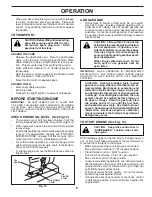
•   Be careful when tilling in hard ground. The tines may 

catch in the ground and propel the tiller forward.  If this 

occurs, let go of the handlebars and do not restrain the 

machine.

MAINTENANCE AND STORAGE

•  Keep machine, attachments, and accessories in safe 

work ing condition.

•  Check shear pins, engine mounting bolts, and other 

bolts at frequent intervals for proper tightness to be 

sure the equip ment is in safe working condition.

•   Never store the machine with fuel in the fuel tank inside 

a building where ignition sources are present, such 

as hot water and space heaters, clothes dryers, and 

the like. Allow the engine to cool before storing in any 

enclosure.

•  Always refer to the operator’s guide instructions for 

im por tant details if the tiller is to be stored for an ex-

tended period.

- IMPORTANT -

CAUTIONS, IMPORTANTS, AND NOTES ARE A MEANS OF 

ATTRACTING ATTENTION TO IMPORTANT OR CRIT I CAL 

IN FOR MA TION IN THIS MANUAL. 

IMPORTANT:  

USED TO ALERT YOU THAT THERE IS A 

POS SI BIL I TY OF DAM AG ING THIS EQUIP MENT.

NOTE: 

Gives essential information that will aid you to bet-

ter understand, incorporate, or execute a particular set of 

instructions.

Look for this symbol to point out im-

 por tant safety precautions.  It means

CAUTION!!!  BE COME ALERT!!!  YOUR 

SAFE TY IS INVOLVED.

CAUTION:  Always disconnect spark 

plug wire and place wire where it can-

 not contact spark plug in order to pre-

 vent ac ci den tal starting when setting 

up, trans port ing, adjusting or making 

re pairs.

SAFETY RULES

Safe Operation Practices for Walk-Behind Powered Ro ta ry Tillers

TRAINING

•  Read the Owner’s Manual care ful ly. Be thor ough ly 

fa mil iar with the controls and the proper use of the 

equip ment. Know how to stop the unit and disengage 

the controls quickly.

•   Never allow children to operate the equipment. Never 

allow adults to op er ate the equipment without proper 

instruction.

•   Keep the area of operation clear of all persons, par-

 tic u lar ly small children, and pets.

PREPARATION

•  Thoroughly inspect the area where the equipment is 

to be used and remove all foreign objects.

•   Disengage all clutches and shift into neutral before 

starting the engine (mo tor).

•  Do not operate the equipment with out wearing ad e -

quate outer gar ments. Wear footwear that will im prove 

footing on slippery surfaces.

•   Handle fuel with care; it is highly flammable. 

•  Use an approved fuel container. 

•  Never add fuel to a running engine or hot engine. 

• 

Fill fuel tank outdoors with extreme care. Never fill fuel 

tank indoors.

•  Replace gasoline cap securely and clean up spilled 

fuel before restarting.

•  Use extension cords and receptacles as specified by 

the manufacturer for all units with electric drive motors 

or electric starting motors.

•   Never attempt to make any adjustments while the 

engine (motor) is running (except where specifically 

rec om mend ed by manufacturer).

OPERATION 

•   Do not put hands or feet near or under rotating parts.

•   Exercise extreme caution when op er at ing on or cross-

 ing gravel drives, walks, or roads. Stay alert for hidden 

hazards or traffic. Do not carry pas sen gers.

•   After striking a foreign object, stop the engine (motor), 

remove the wire from the spark plug, thoroughly in spect 

the tiller for any damage, and repair the damage before 

restarting and op er at ing the tiller.

•  Exercise caution to avoid slipping or falling.

•  If the unit should start to vibrate ab nor mal ly, stop the 

engine (motor) and check immediately for the cause. 

Vi bra tion is generally a warning of trouble.

•  Stop the engine (motor) when leaving the operating 

position.

• 

Take all possible precautions when leav ing the ma chine 

unattended.  Disengage the tines, shift into neutral, and 

stop the engine.

•   Before cleaning, repairing, or inspecting, shut off the 

engine and make certain all moving parts have stopped. 

Disconnect the spark plug wire, and keep the wire away 

from the plug to prevent accidental starting. Disconnect 

the cord on electric motors.

•   Do not run the engine indoors; exhaust fumes are 

dangerous.

•   Never operate the tiller without proper guards, plates, 

or other safety protective devices in place.

WARNING

The engine exhaust from this product con-

 tains chem i cals known to the State of Cal i -

for nia to cause cancer, birth defects, or other 

reproductive harm.

Summary of Contents for CRT900

Page 1: ...Owner s Manual 532 43 95 06 CRT900 ...

Page 2: ... Never allow adults to operate the equipment without proper instruction Keep the area of operation clear of all persons par ticularly small children and pets PREPARATION Thoroughly inspect the area where the equipment is to be used and remove all foreign objects Disengage all clutches and shift into neutral before starting the engine motor Do not operate the equipment without wearing ade quate out...

Page 3: ...NGINE AND SHOULD NOT BE USED ON OR NEAR ANY UNIMPROVED FOREST COVERED BRUSH COVERED OR GRASS COVERED LAND UNLESS THE ENGINE S EXHAUST SYSTEM IS EQUIPPED WITH A SPARK ARRESTER MEETING APPLICABLE LOCAL LAWS IF ANY IFASPARKARRESTERISUSED ITSHOULDBEMAINTAINED IN EFFECTIVE WORKING ORDER BY THE OPERATOR IN THE STATE OF CALIFORNIA A SPARK ARRESTER IS REQUIRED BY LAW SECTION 4442 OF THE CALIFORNIA PUBLIC ...

Page 4: ... been assembled at the factory with exception of those parts left unassembled for shipping purposes To ensure safe and proper operation of your tiller all parts and hardware you assemble must be tightened securely Use the correct tools as necessary to insure proper tightness FRONT OPERATOR S POSITION LEFT RIGHT Fig 1 1 Hairpin Clip 1 Carriage Bolt 3 8 16 UNC x 1 Grade 5 1 Center Locknut 3 8 16 UNC...

Page 5: ...sembly is lowered into position HANDLE ASSEMBLY Fig 3 HANDLE ASSEMBLY GEARCASE NOTCH HANDLE LOCK VIEWED FROM R H SIDE OF TILLER LOOSEN HANDLE LOCK LEVER TO MOVE TIGHTEN HANDLE LOCK LEVER TO HOLD handles_34 CARRIAGE BOLT SLOT GEARCASE HANDLE LOCK FLAT WASHER HANDLE LOCK LEVER PIVOT BOLT LOCKNUT HANDLE BASE Fig 5 Rotate handle assembly down Insert rear carriage bolt first with bolt head on L H side ...

Page 6: ...clip through hole of shift rod to secure Fig 7 Fig 6 END OF CLUTCH CABLE CONTROL BAR CONTROL BAR BRACKET CONTROL BAR BRACKET CLUTCH CABLE ATTACH CLUTCH CABLE See Fig 6 Hook end of clutch cable through hole in control bar bracket CHECK TIRE PRESSURE The tires on your unit were overinflated at the factory for shipping purposes Correct and equal tire pressure is important for best tilling performance...

Page 7: ...NTS Our tillers conform to the safety standards of the American National Standards Institute CHOKE CONTROL Used when starting a cold engine DEPTH STAKE Controls depth at which tiller will dig DRIVE CONTROL BAR Used to engage tines LEVELING SHIELD Levels tilled soil RECOIL STARTER HANDLE Used to start the engine SHIFT LEVER Used to shift transmission gears SHIFT LEVER INDICATOR Shows which gear the...

Page 8: ...ler movement HARD TO SHIFT GEARS Brieflyengagedrivecontrolbarandreleaseorrocktiller forward and backward until are able to shift gears DEPTH STAKE See Fig 10 The depth stake can be raised or lowered to allow you more versatile tilling and cultivating or to more easily transport your tiller Fig 9 depth_stake_2 TILLING See Fig 11 Release depth stake pin Pull the depth stake up for increased tilling ...

Page 9: ...ne has run out of fuel it will take extra pulls of the recoil starter to move fuel from the tank to the engine Make sure spark plug wire is properly connected Move shift lever indicator to N neutral position Place throttle control in FAST position Turn fuel shut off valve 1 4 turn to open position Move choke control to choke position Grasp recoil starter handle with one hand and grasp tiller handl...

Page 10: ...oreplanting Loose unpackedsoilhelps root growth Best tilling depth is 4 to 6 10 15 cm A tiller will also clear the soil of unwanted vegetation The decomposition of this vegetable matter enriches the soil Depending on the climate rainfall and wind it may be advisable to till the soil at the end of the growing season to further condition the soil You will find tilling much easier if you leave a row ...

Page 11: ...oil level Check tine operation Check for loose fasteners LUBRICATION Keep unit well lubricated See LUBRICATION CHART SAE 30 OR 10W 30 MOTOR OIL REFER TO MAINTENANCE ENGINE SECTION EP 1 GREASE LUBRICATION CHART WHEEL HUB ENGINE IDLER BRACKET LEVELING SHIELD HINGES DEPTH STAKE PIN RH GEAR CASE GREASE FITTING MAINTENANCE SCHEDULE FILL IN DATES AS YOU COMPLETE REGULAR SERVICE Check Engine Oil Level Ch...

Page 12: ... grade according to your expected temperature NOTE Although multi viscosity oils 5W 30 10W 30 etc improve starting in cold weather these multi viscosity oils will result in increased oil consumption when used above 40 F 4 C Check your engine oil level more frequently to avoid possible engine damage from running low on oil Change the oil after every 25 hours of operation or at least once a year if ...

Page 13: ...illing sea son or after every 50 hours of use whichever comes first Spark plug type and gap setting is shown in PRODUCT SPECIFICATIONS on page 3 of this manual TRANSMISSION Once a season lubricate the right hand side gear case grease fitting with 1 oz of EP 1 Grease CLEANING Do not clean your tiller when the engine and transmission are hot We do not recommend using pressurized water garden hose et...

Page 14: ...ND CLEVIS PIN TO REMOVE BELT GUARD See Fig 22 NOTE For ease of removal remove hairpin clip and clevis pin from left wheel Pull wheel out from tiller about 1 inch Remove two 2 screws from side of belt guard Remove hex nut and washer from bottom of belt guard located behind wheel Pull belt guard out and away from unit Replace belt guard by reversing above procedure TIRE CARE CAUTION When mounting ti...

Page 15: ...T BE IN GROOVE ON TOP OF IDLER PULLEY NOTE POSITION OF BELT TO GUIDES Check belt adjustment as described below Replace belt guard Reposition wheel and replace clevis pin and hairpin clip Fig 23 GROUND DRIVE BELT ADJUSTMENT See Fig 23 For proper belt tension the extension spring should have about 5 8 inch stretch when drive control bar is in ENGAGED position This tension can be attained as follows ...

Page 16: ...arpened tine edges will rotate rearward from above tine_2 TRANSMISSION TINE TINE 3 1 2 MAX Fig 26 SHARP EDGE HAIRPIN CLIP SHARP EDGES SHARP EDGE SHARP EDGE SHARP EDGE COUNTER TINE ROTATION TINE REPLACEMENT See Figs 24 25 and 26 CAUTION Tines are sharp Wear gloves or other protection when han dling tines A badly worn tine causes your tiller to work harder and dig more shallow Most important worn ti...

Page 17: ...uretor does need adjustment contact your nearest authorized service center department IMPORTANT NEVER TAMPER WITH THE ENGINE GOVERNOR WHICHISFACTORYSETFORPROPERENGINE SPEED OVERSPEEDINGTHEENGINEABOVETHEFACTORY HIGH SPEED SETTING CAN BE DANGEROUS IF YOU THINK THE ENGINE GOVERNED HIGH SPEED NEEDS ADJUSTING CONTACTYOURNEARESTAUTHORIZEDSERVICECENTER DEPARTMENT WHICH HAS THE PROPER EQUIPMENT AND EXPERI...

Page 18: ...y starting the engine and let it run until the fuel lines and carburetor are empty Never use engine or carburetor cleaner products in the fuel tank or permanent Use fresh fuel next season NOTE Fuel stablizer is an acceptable alternative in minimizing the formation of fuel gum deposits during storage Add stabilizer to gasoline in fuel tank or storage container Always follow the mix ratio found on s...

Page 19: ... and clean carburetor 6 Stale or dirty fuel 6 Empty fuel tank and refill tank with fresh clean gasoline 7 Water in fuel 7 Empty fuel tank and carburetor and refill tank with fresh clean gasoline 8 Clogged fuel tank 8 Remove fuel tank and clean 9 Spark plug wire loose 9 Connect and tighten spark plug wire 10 Dirty engine air screen 10 Clean engine air screen 11 Dirty clogged muffler 11 Clean replac...

Page 20: ... 44 Clamp Bar Control KEY PART NO NO DESCRIPTION 2 532 42 76 43 Grip Handle 4 532 15 92 28 Bar Assembly Control 6 532 18 06 85 Panel Control 8 871 19 10 08 Screw Truss Hd 10 24 unc x 1 2 10 532 12 47 97 Grip Handle 11 532 12 47 88 Clip Hairpin 12 532 08 13 28 Bolt Shoulder 13 532 18 74 97 Handle Shift 14 532 10 93 13 Grommet Rubber 15 532 10 93 37 Rod Shift 16 872 11 06 08 Bolt Carriage 3 8 16 x 1...

Page 21: ...47 88 Clip Hairpin 26 532 16 67 92 Guard Belt REPAIR PARTS TILLER MODEL NUMBER CRT900 96093001301 PRODUCT NUMBER 960 93 00 13 MAINFRAME LEFT SIDE KEY PART NO NO DESCRIPTION 27 532 13 28 01 Belt V 28 532 10 46 79 Pulley Idler 29 812 00 00 32 Ring Klip 30 532 15 92 29 Bracket Idler 31 532 10 21 94 Bolt Fin Hex 3 8 16 unc x10 32 532 10 21 41 Shaft Idler Arm 33 874 76 06 16 Bolt Hex 3 8 16 x 1 34 532 ...

Page 22: ... Hex 5 16 18 x 1 1 2 11 532 12 47 88 Clip Hairpin 12 532 12 68 75 Rivet Drilled 13 532 10 21 90 Tire 532 15 07 40 Rim 532 12 47 18 Tire Valve 15 Engine Briggs Stratton Model No 121002 1380 B8 Order parts from Engine Manufacturer 44 873 51 06 00 Nut Keps Hex 3 8 16 unc MAINFRAME RIGHT R NOTE All component dimensions given in U S inches 1 inch 25 4 mm For engine service and replacement parts call th...

Page 23: ...L NUMBER CRT900 96093001301 PRODUCT NUMBER 960 93 00 13 TRANSMISSION KEY PART NO NO DESCRIPTION 30 532 15 07 37 Ground Shaft Assembly 31 532 14 30 08 Bearing Shaft Ground Drive R H 32 532 10 63 88 Spacer 0 70 x 1 00 x 1 150 33 532 10 21 21 Sprocket and Gear Assembly 34 532 10 21 12 Shaft Reduction 2nd 35 532 10 21 01 Screw Whiz Lock 5 16 18 x 3 1 2 36 532 15 43 55 Sprocket Assembly w Bearing Inclu...

Page 24: ...ing Klip 5 532 18 08 47 Bolt Rdhd Sqnk 5 16 18 x 3 4 6 532 00 83 94 Spring 7 532 00 83 92 Bracket Latch 8 532 10 92 30 Spring Depth Stake 9 532 13 88 63 Shield Tine 13 872 11 05 10 Bolt Carriage 5 16 18 x 1 1 4 14 532 12 43 43 Bracket Shield Tine 16 873 90 04 00 Nut Hex Flange 1 4 20 unc 18 872 04 04 10 Bolt Carriage 1 4 20 x 1 1 4 Gr 19 532 10 27 01 Grip 20 873 22 06 00 Nut Hex 3 8 16 21 532 10 2...

Page 25: ...32 13 27 21 Assembly Hub and Plate L H 8 874 61 06 16 Bolt Hex 3 8 24 x 1 9 532 00 44 60 Tine Outer R H 10 532 13 27 22 Assembly Hub and Plate R H 11 532 00 65 55 Tine Inner R H 34 873 54 06 00 Nut Crownlock 3 8 24 NOTE All component dimensions given in U S inches 1 inch 25 4 mm REPAIR PARTS TILLER MODEL NUMBER CRT900 96093001301 PRODUCT NUMBER 960 93 00 13 TINE ASSEMBLY TINE IPB R ...

Page 26: ...2 10 21 80 Decal Shift Indicator 7 532 42 29 72 Decal Warning 8 532 43 22 78 Decal Engine Air Cleaner 9 532 12 00 76 Decal Warning Rotating Tines 10 532 40 91 43 Decal Engine Fuel Tank 8 5 532 43 95 06 Owner s Manual English 532 43 95 07 Owner s Manual French KEY PART NO NO DESCRIPTION 3 2 REPAIR PARTS TILLER MODEL NUMBER CRT900 96093001301 PRODUCT NUMBER 960 93 00 13 DECALS 6 9 5 7 8 10 4 1 ...

Page 27: ...27 SERVICE NOTES ...

Page 28: ...nty obligation of the other manufacturer s engines b Transmissions Except where otherwise indicated on Exhibit A Transmission Transaxle including Drive Systems are not covered by this warranty In most cases these items are NOT manufactured by Husqvarna in which case they may be covered separately by their respective manufacturer s warranties if one is provided and included with the product at the ...

Page 29: ...emoved damaged air filter excessive dirt abrasives salt water moisture corrosion rust varnish stale fuel or any adverse reaction due to incorrect storage procedures n Failures due to improper set up pre delivery service or repair service by anyone other than an authorized Husqvarna servicing dealer during the warranty period o Dirt contaminated grease or oil use of incorrect type of greases or oil...

Page 30: ...TY Other Non Expendable Components 2 Years NO WARRANTY NO WARRANTY Snow Throwers Engine Residential Zero Turn Mowers MZ EZ Product Component Residential Zero Turn Mowers RZ Only Engine Other Non Expendable Components 2 Years 90 days 90 days Tillers Engine Battery 1 Year Pro rated NO WARRANTY NO WARRANTY Other Non Expendable Components 2 Years NO WARRANTY NO WARRANTY Tiller Tines NO WARRANTY NO WAR...

Page 31: ...tery 1 Year 1 Year 1 Year P t A i if h d All other Pressure Washers 6027PW 9032PW 1340PW Parts Accessories if purchased Accessories e g grass catcher bumper guard accessories etc 1 Year NO WARRANTY NO WARRANTY Parts e g belts blades etc 30 days NO WARRANTY NO WARRANTY Parts Accessories if replaced in Warranty Service Replacement parts and or accessories provided under this Limited Warranty are war...

Page 32: ...10 11 10 CL Printed in the U S A ...

Reviews: